 EN
EN AR
AR HR
HR CS
CS DA
DA NL
NL FI
FI FR
FR DE
DE EL
EL IT
IT JA
JA KO
KO NO
NO PL
PL PT
PT RU
RU ES
ES SV
SV IW
IW VI
VI TH
TH TR
TR FA
FA MS
MS
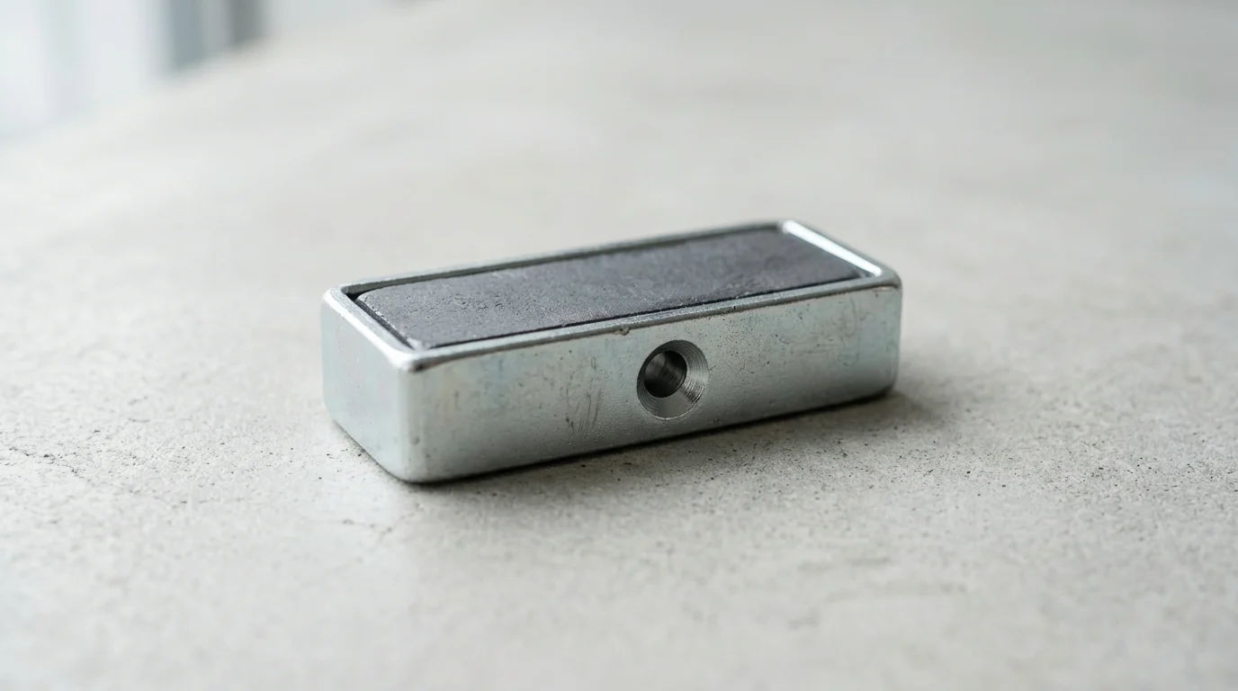
In modern factories, every millimeter of fixture space and every second of setup time matters. Rectangular pot magnets offer a compact way to generate strong, repeatable holding force in places where bulky clamps or round magnets create design limits. By combining a magnet with a steel channel, these assemblies concentrate magnetic flux, protect the core, and improve stability under industrial loads. This article explains how their shape, housing, and mounting style help manufacturers increase holding force, reduce unwanted movement, and simplify automation systems. It also highlights where they deliver the most value, from robotic grippers and conveyor tracks to precision jigs and sheet metal handling.
Why Rectangular Pot Magnets Matter in Industrial Holding
Industrial holding applications demand robust, space-efficient solutions capable of securing heavy components under intense mechanical stress. Traditional clamping mechanisms often require extensive setup time and physical space, which can hinder automated processes and compact machinery design. Magnetic assemblies engineered for high-performance retention have become critical components in modern manufacturing, delivering rapid engagement and reliable holding forces that frequently exceed 50 kilograms in highly compact form factors.
Among the most effective solutions are rectangular magnetic assemblies housed in steel channels. These components are specifically designed to maximize holding force within a linear footprint, making them indispensable for applications where round magnets cannot fit or fail to provide adequate resistance against rotational forces. By integrating these specialized magnetic assemblies into fixtures, engineers can achieve significant improvements in process efficiency.
How They Improve Fixture Reliability
Fixture reliability is paramount in machining and assembly environments where microscopic shifts in component positioning lead to critical defects. Standard permanent magnets provide strong direct pull force on ferromagnetic materials, but they are highly susceptible to lateral sliding when subjected to shear forces. A bare magnet typically offers a shear resistance equal to only 15% to 20% of its direct pull force, making it unreliable for dynamic industrial holding.
The integration of a steel housing fundamentally changes this dynamic. The steel channel protects the brittle magnetic material from mechanical impact and provides a critical flux return path. When properly integrated into a fixture, the rectangular profile prevents the assembly from rotating under load. This anti-rotational characteristic ensures that components remain exactly where they are placed, drastically reducing the defect rate in precision applications and extending the overall lifespan of the workholding setup.
Where They Create the Most Value
The structural design of a Rectangular Pot Magnet creates the most value in environments constrained by narrow geometries. Automated conveyor systems, robotic end-of-arm tooling, and linear tracks frequently feature slim rails and tight clearances. Round magnets of equivalent holding force would overhang these narrow profiles, interfering with moving parts or requiring cumbersome adapter plates.
By utilizing a rectangular form factor , manufacturers can align the long axis of the magnet with the structural rails of their machinery. This maximizes the contact area within a restricted width. For instance, in automated sheet metal handling, a series of rectangular assemblies can be embedded flush along the gripper arm, distributing forces evenly across the payload without adding unnecessary bulk or weight to the robotic system.
Key Benefits for Production Environments
Integrating these magnetic components into production environments yields several quantifiable operational benefits. First, the elimination of manual clamps and pneumatic actuators simplifies the workholding architecture. This reduction in moving parts translates directly to lower maintenance costs and fewer points of failure, which is critical for facilities aiming to maximize overall equipment effectiveness (OEE).
Furthermore, the flush-mounting capabilities of these assemblies allow for seamless integration into workbenches and jigs. Because the magnetic field is strictly concentrated on the exposed face, stray magnetic flux leaking from the sides or back of the assembly is greatly reduced, though not entirely eliminated near the edges. This minimizes the unintended attraction of metal shavings or nearby tools, keeping the workspace clean. However, operators must be trained on safety protocols, as these powerful assemblies present severe pinch hazards and can be difficult to remove once fully engaged. Production environments that transition to these optimized magnetic fixtures frequently report a 15% to 30% reduction in setup times and a marked improvement in repetitive placement accuracy.
How Rectangular Pot Magnets Work

Understanding the underlying physics of channeled magnetic assemblies is essential for predicting their performance in real-world applications. Unlike raw magnets, these engineered components rely on a carefully calculated interaction between the permanent magnet and its surrounding metallic enclosure to manipulate and amplify the magnetic field.
How the Steel Housing Concentrates Magnetic Flux
At the core of the design is the principle of magnetic flux concentration. A standard raw magnet emits a magnetic field from both its north and south poles, with the flux lines traveling through the surrounding air. By embedding the magnet inside a U-shaped steel channel or pot, the steel acts as a highly permeable magnetic circuit. It redirects the flux lines from the concealed pole and channels them to the open face of the assembly. This redirection concentrates the entire magnetic energy onto a single active surface, effectively increasing the direct pull force by up to 300% compared to an unhoused magnet of the exact same volume.
Why Contact Area, Air Gap, and Surface Condition Matter
The theoretical holding force of a magnet assumes specific ideal test conditions: perfect, flush contact with a thick, flat, low-carbon steel surface. In reality, the contact area, the presence of an air gap, and the surface condition of the workpiece drastically alter performance. Magnetic force follows an inverse-square law regarding distance; therefore, even a microscopic separation between the magnet and the target material causes a severe drop in retention power.
For instance, introducing a mere 0.5mm air gap—often caused by paint layers, rust, or uneven surfaces—can reduce the effective holding force by 50% or more. Similarly, surface roughness plays a critical role. A workpiece with a roughness average (Ra) exceeding 6.3 µm prevents intimate contact, creating localized micro-air gaps. Ensuring a clean, flat, and unpainted mating surface is non-negotiable for achieving the rated pull force in industrial settings.
How Magnet Materials Affect Performance
The choice of magnetic alloy directly dictates the assembly's strength, temperature resistance, and cost. Neodymium (NdFeB) is the industry standard for high-strength applications, offering the highest magnetic energy product available. However, standard Neodymium grades begin to lose magnetization at temperatures exceeding 80°C. For extreme environments, alternative materials like Samarium Cobalt (SmCo) or specialized high-temperature Neodymium grades are required to maintain operational integrity.
| Magnet Material | Maximum Operating Temperature | Relative Holding Force | Relative Cost |
|---|---|---|---|
| Standard Neodymium (NdFeB) | 80°C | Very High | Moderate |
| High-Temp Neodymium (UH/EH) | 180°C to 200°C | High | High |
| Samarium Cobalt (SmCo) | 250°C to 350°C | High | Very High |
| Ferrite (Ceramic) | 250°C | Low | Low |
How to Compare Rectangular Pot Magnet Specifications
Selecting the correct magnetic assembly requires a thorough evaluation of technical specifications to ensure compatibility with the intended application. Procurement engineers must balance the required holding capacity against spatial limitations, mounting configurations, and overall budget constraints.
Pull Force, Size, and Mounting Options
The primary metric for any magnetic assembly is its rated pull force, which typically ranges from 10 kilograms for compact models to over 150 kilograms for heavy-duty industrial variants. However, this force must be contextualized by the physical dimensions of the unit. A longer, wider assembly will naturally provide higher force, but it must fit within the designated machining slot or robotic gripper profile.
Mounting options are equally critical for secure installation. A Rectangular Countersunk Magnet features a tapered hole designed for flat-head screws , allowing the fastener to sit perfectly flush with the magnetic surface. Alternatively, a Counterbored Pot Magnet accommodates standard socket-head cap screws. The choice between countersunk and counterbored designs depends entirely on the standardized fasteners used in the facility and the required depth of the mounting hardware.
Rectangular vs Round Pot Magnets
While round pot magnets are ubiquitous, rectangular variants offer distinct mechanical advantages in specific scenarios. The primary differentiator is spatial efficiency and resistance to torque. Round magnets require a wide circular footprint, whereas rectangular models can be nested into narrow channels or along the edges of a chassis. Furthermore, a single rectangular magnet secured with two screws provides inherent anti-twist properties, whereas a single round magnet fixed via a central stud can act as a pivot point if subjected to rotational forces.
| Feature | Rectangular Pot Magnets | Round Pot Magnets |
|---|---|---|
| Footprint Efficiency | High (fits in narrow linear channels) | Moderate (requires wider surface area) |
| Rotational Resistance | Excellent (inherent anti-twist with two holes) | Poor (can spin on a single central axis) |
| Typical Mounting | Multiple countersunk or counterbored holes | Single central threaded hole, stud, or countersink |
| Ideal Application | Linear tracks, narrow robotic grippers, edge clamping | General lifting, point-load fixtures, broad surfaces |
Trade-Offs Between Holding Force, Cost, and Durability
Engineering a magnetic holding solution involves inevitable trade-offs. Maximizing holding force usually dictates the use of high-grade Neodymium, which increases the unit cost compared to Ferrite alternatives. However, the superior strength-to-size ratio of Neodymium often allows engineers to use smaller, lighter assemblies, thereby saving costs on the surrounding structural materials and reducing the payload on automated arms.
Durability is another vital consideration. While the magnetic material itself is brittle and prone to chipping, the mild steel housing absorbs mechanical shocks and impacts during repetitive clamping cycles. Specifying a thicker steel housing increases the overall durability and lifespan of the component, but it also adds weight and slightly reduces the internal volume available for the magnet, representing a necessary compromise between ruggedness and absolute magnetic power.
How to Install and Use Rectangular Pot Magnets Correctly
Even the highest-quality magnetic assemblies will fail to perform if installed incorrectly. Proper installation protocols are required to maximize the contact area, protect the brittle magnetic core from mechanical stress, and ensure long-term reliability in demanding industrial environments.
Mounting and Alignment Best Practices
Achieving a flush mount is the gold standard for magnetic fixture installation. The receiving slot milled into the workpiece or jig must be machined to precise tolerances, typically within +/- 0.1mm of the magnet's dimensions. If the magnet sits too deep, an artificial air gap is created, plummeting the holding force. If it protrudes, it bears the full brunt of mechanical impacts, risking fracture.
Torque management during the fastening process is equally critical. The internal magnetic material is brittle and cannot withstand excessive compression. When securing the assembly, operators must strictly adhere to torque specifications. For example, depending on the assembly's size and housing material, standard M4 mounting screws should generally not exceed 1.5 Nm of torque. Over-tightening can distort the steel housing or crack the internal magnet, instantly compromising the unit's structural integrity and magnetic field distribution.
How to Optimize Magnet Placement
Strategic placement of magnetic assemblies dictates the overall stability of the fixture. To maximize leverage resistance, magnets should be positioned at the extremities or corners of the workpiece rather than clustered in the center. This distribution provides a wider stance against peeling forces, which are far more detrimental to magnetic holds than direct vertical pulls.
Additionally, engineers must account for the spacing between multiple magnetic units. If placed too closely together, the magnetic fields of adjacent assemblies can interact and overlap, potentially causing flux leakage or field cancellation. As a general guideline, maintaining an adequate minimum spacing—such as 40mm to 50mm for typical high-strength assemblies—ensures that each unit operates at peak individual efficiency without magnetic interference.
Common Installation Mistakes to Avoid
One of the most frequent installation errors is the use of incorrect fastening hardware. Securing a magnetic assembly with standard carbon steel screws can create a magnetic short circuit. The steel screw draws flux away from the active face and into the fastener itself, noticeably reducing the effective pull force. Installers must exclusively use non-magnetic fasteners, such as 304 or 316 stainless steel screws, to ensure the magnetic energy remains directed toward the target workpiece.
Another common mistake is ignoring the operating environment during installation. In applications involving cutting fluids, coolants, or high humidity, capillary action can draw corrosive liquids into the microscopic gaps between the magnet and its steel housing. Failing to apply a thin layer of industrial sealant or anti-corrosion compound to the mounting pocket before installation can lead to rapid oxidation, causing the magnet to swell and eventually shatter its housing.
How to Choose a Rectangular Pot Magnet Supplier
Sourcing industrial-grade magnetic components requires vetting suppliers on their manufacturing capabilities, quality control rigor, and ability to meet specific production timelines. A reliable supplier acts as an engineering partner, ensuring that the magnetic assemblies perform consistently across thousands of operational cycles.
Quality, Compliance, and Testing Standards
High-quality manufacturing begins with stringent compliance and testing standards. Reputable suppliers operate under ISO 9001 quality management systems, ensuring traceability and magnetization direction consistency from raw material procurement to final assembly. Furthermore, components destined for global markets must comply with environmental directives such as RoHS and REACH, certifying that the assemblies are free from hazardous substances like lead and cadmium.
Testing protocols are the true measure of a supplier's reliability. Standardized pull force testing should be conducted using a universal testing machine on a 10mm thick, flat, low-carbon steel plate with a surface roughness of Ra 1.6 µm or better. Suppliers should also provide BH curve testing data and documentation proving their assemblies meet the rated specifications with highly controlled defect rates (often targeted at<0.1% for premium batches), ensuring absolute consistency across large orders.
Lead Time, Customization, and Coating Durability
Lead times and supply chain stability are critical factors for production planning. Standard off-the-shelf rectangular assemblies typically carry lead times of 2 to 4 weeks, whereas custom-engineered solutions may require 6 to 8 weeks for tooling, prototyping, and mass production. Buyers must evaluate a supplier's inventory management, their capacity to scale production, and their expertise in handling air-shipping restrictions for NdFeB assemblies, which must comply with strict IATA magnetic packaging regulations.
Coating durability is another key differentiator. Industrial environments subject magnets to moisture, chemicals, and abrasion. A premium supplier will offer robust surface treatments, such as a triple-layer Nickel-Copper-Nickel (Ni-Cu-Ni) coating applied at a thickness of 10 to 20 microns. For highly corrosive environments, suppliers should provide options for epoxy or specialized zinc plating capable of withstanding 48 to 72 hours of continuous salt spray testing without showing signs of red rust.
When to Choose Standard or Custom Magnets
The decision between procuring standard or custom magnetic assemblies hinges on application requirements and order volumes. Standard units are highly cost-effective and readily available, making them ideal for rapid prototyping, general-purpose fixturing, or production runs where the minimum order quantity (MOQ) is below 500 units. They offer predictable performance and immediate integration into conventional designs.
Conversely, custom assemblies are necessary when dealing with extreme operating temperatures, highly specific spatial constraints, or unique mounting hole placements. If an application requires a specialized Samarium Cobalt core for a 300°C welding environment or a non-standard length to fit a proprietary robotic arm, custom manufacturing is the only viable route. While custom orders typically require higher MOQs—often exceeding 1,000 units—and involve initial tooling costs, they deliver an optimized solution that perfectly aligns with specialized industrial demands.
Further reading:
Key Takeaways
- Use rectangular pot magnets when a narrow linear footprint is required and round magnets would overhang rails, gripper arms, or compact fixtures.
- Select steel-housed magnetic assemblies to concentrate magnetic flux, protect brittle magnet material, and improve holding reliability in industrial environments.
- Account for shear forces during fixture design because bare magnets may resist only about 15% to 20% of their rated direct pull force.
- Align the long axis of a rectangular pot magnet with machine rails or structural members to maximize contact area and reduce unwanted rotation.
- Integrate flush-mounted rectangular pot magnets into jigs, workbenches, and robotic tooling to reduce moving parts and lower maintenance requirements.
Frequently Asked Questions
What is a rectangular pot magnet used for?
A rectangular pot magnet is used for compact industrial holding, positioning, lifting, and fixturing where a long, narrow footprint is required. It is especially useful on rails, gripper arms, conveyor fixtures, and jigs where round magnets may not fit efficiently.
Why does the steel housing increase holding performance?
The steel channel protects the magnet and redirects magnetic flux toward the contact surface. This concentrates the magnetic field, improves pull force, and helps the assembly perform more reliably in demanding industrial fixtures.
How do rectangular pot magnets help prevent rotation?
Their elongated shape resists twisting better than round magnets in linear fixtures. When aligned with rails or slots, the rectangular body provides anti-rotational stability, helping parts stay accurately positioned under load.
Are rectangular pot magnets better than bare magnets?
For industrial holding, they are often more reliable. Bare magnets may offer strong pull force but can slide under shear loads, often resisting only about 15% to 20% of direct pull. Pot magnet housings improve protection, positioning, and usable holding performance.
Where can I find rectangular pot magnet options?
You can review rectangular pot magnet products and specifications on rcmagnet.com, including models designed for narrow fixtures, automation equipment, and industrial workholding applications.