 EN
EN AR
AR HR
HR CS
CS DA
DA NL
NL FI
FI FR
FR DE
DE EL
EL IT
IT JA
JA KO
KO NO
NO PL
PL PT
PT RU
RU ES
ES SV
SV IW
IW VI
VI TH
TH TR
TR FA
FA MS
MS
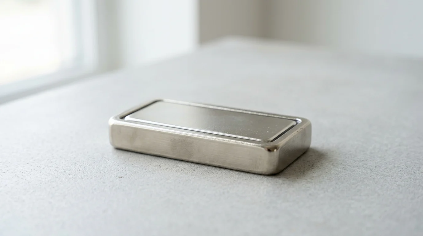
In high-mix manufacturing, every clamp adjustment, fixture change, and workpiece repositioning step adds hidden cost to the production cycle. Rectangular pot magnets address that problem by combining permanent magnetic force with a protective steel housing that channels pull to a single working face. The result is compact, durable workholding that can speed setup, simplify modular fixture design, and reduce reliance on bulky mechanical clamps. This article explains how the rectangular form factor improves resistance to rotation, fits into common tooling structures, and supports faster welding, machining, assembly, and inspection workflows. It also highlights where magnetic holding should be paired with stops, pins, and proper sizing for repeatable performance.
Strategic Advantages of Rectangular Pot Magnets
The integration of a Rectangular Pot Magnet into manufacturing workflows represents a critical shift from purely mechanical fastening to advanced magnetic workholding. By enclosing a high-strength permanent magnet within a steel channel or housing, these components redirect and concentrate the magnetic flux to a single active face. This design not only protects the brittle magnetic core from impact but also significantly multiplies the holding force compared to raw magnets. Industrial facilities leveraging these specialized workholding solutions frequently report substantial fixture setup time reductions, according to industry benchmarks, directly translating to higher throughput and reduced machine downtime.
In modern manufacturing environments, the demand for modular and rapidly reconfigurable tooling has never been higher. Production lines must pivot between different product SKUs with minimal delay. Incorporating rectangular magnetic assemblies into jigs and fixtures allows operators to secure ferrous components rapidly, bypassing the need for complex mechanical clamping systems. As detailed later in this guide, the linear geometry of these magnets provides a distinct advantage over circular alternatives, offering superior resistance to rotational forces and fitting seamlessly into standard structural aluminum extrusions and milled steel channels.
Faster Setup and Repositioning
Traditional mechanical clamping requires operators to manually tighten bolts, actuate toggle clamps, or adjust pneumatic actuators, all of which consume valuable cycle time. By replacing these mechanisms with rectangular magnetic assemblies, manufacturers eliminate the threading and unthreading processes entirely. A single operator can position a heavy steel workpiece against a magnetic fixture in seconds, achieving immediate and reliable securement. Tooling manufacturers report that time studies in automotive assembly applications have demonstrated magnetic positioning can save valuable time per clamping cycle, a metric that compounds into hundreds of hours of saved labor annually per production cell.
Furthermore, repositioning workpieces during multi-stage machining or welding processes becomes significantly more efficient. Unlike switchable electromagnets, permanent pot magnets provide constant holding force; therefore, repositioning requires mechanically overcoming the holding force or sliding the part laterally. This straightforward mechanical disengagement allows for rapid manual or automated handling, minimizing the non-value-added time spent on machine setup and teardown. The strong directional pull of the channeled housing ensures that once the part is placed within the active zone, it is drawn firmly against the fixture. However, because magnetic attraction pulls toward the center of mass, precision locating still requires physical stops, pins, or machined nests to ensure repeatable accuracy across thousands of cycles.
Common Tooling and Fixture Applications
The versatility of the rectangular form factor makes it an ideal candidate for a wide array of tooling and fixture applications. In welding fabrication, these magnets are frequently employed as grounding clamps or right-angle holding jigs, maintaining perfect 90-degree alignments between heavy steel plates prior to tack welding. Their low profile allows them to slide into tight clearances where bulky mechanical clamps would obstruct the path of the welding torch or robotic arm. A standard 120mm length assembly can easily support heavy steel plates against gravity during vertical welding operations.
Beyond welding, these magnetic components are integral to automated assembly lines and inspection stations. Quality control fixtures utilize them to temporarily hold stamped metal parts firmly against datum surfaces for coordinate measuring machine (CMM) probing. The linear footprint aligns perfectly with the edges of sheet metal components, providing continuous support along the perimeter rather than localized pinch points. This continuous line of magnetic force prevents thin-gauge materials from bowing or warping during inspection, helping to maintain dimensional measurement accuracy to within tight tolerances, provided the overall fixture design and datum surfaces are properly engineered.
Key Specifications for Rectangular Pot Magnets
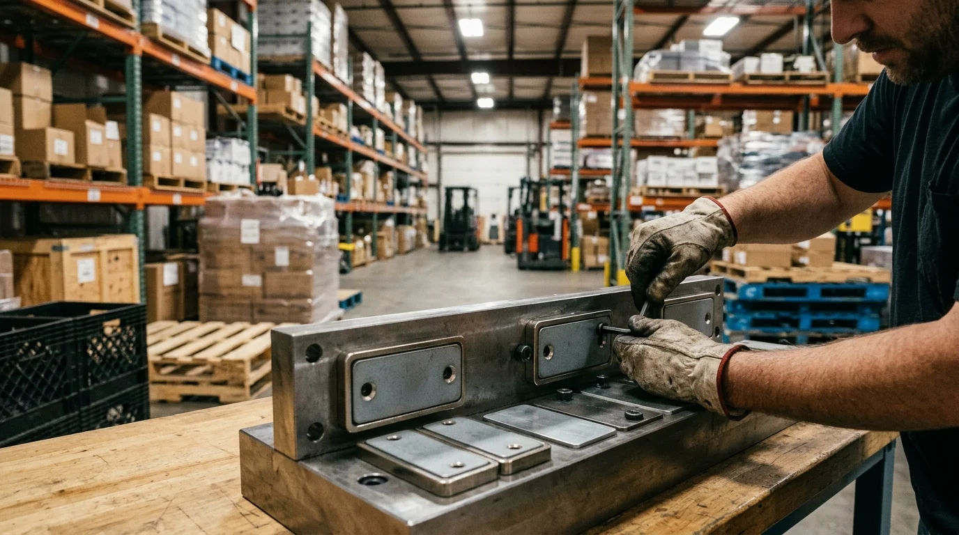
Understanding the foundational specifications of a Rectangular Pot Magnet is essential for engineers tasked with designing robust workholding systems. The performance of these devices is not solely determined by the grade of the internal magnet, but rather by the highly engineered synergy between the magnetic core and its steel enclosure. By carefully selecting the appropriate dimensions, pull forces, and thermal ratings, tooling designers can optimize their fixtures for maximum holding power while minimizing spatial footprint and overall weight.
The interplay between geometric constraints and magnetic output dictates the success of a fixture design. Engineers must evaluate the specific environmental conditions, including ambient temperatures and exposure to corrosive cutting fluids, to specify the correct protective coatings and magnetic alloys. Failure to account for these variables can lead to premature demagnetization, coating compromise, or structural failure of the workholding setup, resulting in costly production delays and compromised safety.
Steel Housing, Magnet Core, and Pole Layout
The defining characteristic of these magnetic assemblies is the steel housing , typically shaped as a U-channel, which encases the permanent magnet core. This steel shell serves a dual purpose: it acts as a robust mechanical shield against impacts, and more importantly, it functions as a flux circuit. The steel redirects the magnetic field lines that would normally emit from the sides and back of the magnet, channeling them entirely to the front active face. This concentration of magnetic energy can amplify the effective pull force significantly, based on standard magnetic circuit calculations, compared to a bare magnet of identical volume.
The pole layout within this channel is equally critical. In a standard configuration, the steel housing itself acts as one magnetic pole (e.g., North), while the exposed face of the internal magnet acts as the opposite pole (e.g., South). When a ferrous workpiece bridges the gap between the magnet and the steel lip of the housing, it completes the magnetic circuit, resulting in a highly localized and incredibly strong clamping force. This closed-loop circuit minimizes stray magnetic fields, preventing unwanted attraction to nearby tooling or metal shavings, which is crucial in precision machining environments.
Pull Force, Size, Temperature, and Coating
When specifying these components, engineers must evaluate a matrix of pull forces, dimensional constraints, and environmental limits. Standard lengths range from compact 20mm units designed for tight spaces to extended 200mm bars capable of securing large sheet metal panels. Operating temperature is a critical threshold; standard Neodymium (NdFeB) cores begin to suffer irreversible flux loss at temperatures exceeding 80°C. For elevated temperature environments, such as hot stamping or pre-heated welding fixtures, high-coercivity variants are required, capable of withstanding up to 150°C or even 200°C without degradation. Protective coatings, typically a 10-20 micron layer of Nickel-Copper-Nickel (NiCuNi) or zinc plating, are essential to prevent the highly reactive neodymium from oxidizing, especially in environments exposed to corrosive cutting fluids where coating failure can lead to rapid magnet degradation.
The following table illustrates typical specifications across various size classes to assist in baseline fixture planning:
| Length × Width × Height (mm) | Internal Magnet Material | Max Operating Temp (°C) | Direct Pull Force (kg) | Typical Application |
|---|---|---|---|---|
| 40 × 8 × 6 | NdFeB (N35) | 80 | 12 | Light sensor mounting |
| 80 × 10 × 8 | NdFeB (N42) | 80 | 25 | Sheet metal alignment |
| 120 × 15 × 6 | NdFeB (N45SH) | 150 | 45 | High-temp welding jigs |
| 200 × 20 × 10 | NdFeB (N52) | 80 | 90 | Heavy plate securement |
When to Choose Neodymium Rectangular Pot Magnets
The decision to utilize Neodymium variants over traditional Ferrite or Alnico magnets comes down to the necessity for extreme strength-to-volume ratios. Neodymium iron boron (NdFeB) is the strongest permanent magnetic material commercially available, allowing for incredibly low-profile fixtures that do not interfere with tooling paths. When vertical clearance is at a premium, engineers frequently specify a Rectangular Countersunk Magnet , which features pre-drilled holes with chamfered edges . This design allows standard M3 or M4 flat-head screws to sit perfectly flush with the magnetic face, ensuring zero air gap between the magnet and the workpiece.
These flush-mountable neodymium assemblies are particularly valuable in progressive die stamping and injection molding setups. In these applications, the tooling blocks must mate perfectly with zero protrusion from the fasteners. The immense holding power of neodymium ensures that even under the intense vibrational loads of a heavy press, the magnetic inserts remain rigidly secured. Furthermore, the high coercivity of neodymium resists demagnetization from external opposing fields, maintaining consistent clamping force throughout hundreds of thousands of production cycles.
Rectangular Pot Magnets vs Alternative Workholding
Selecting the optimal workholding strategy requires a rigorous comparison of available technologies. While traditional mechanical systems have been the industry standard for decades, magnetic workholding introduces unique efficiencies that fundamentally alter production economics. By evaluating the specific operational mechanics, spatial footprints, and automation compatibility of various clamping methods, facility managers can identify the exact scenarios where linear magnetic assemblies outperform conventional alternatives.
The transition from mechanical to magnetic workholding is not universally applicable to all materials—it inherently requires ferrous workpieces. Furthermore, engineers must account for critical machining caveats: magnetic workholding inherently magnetizes ferrous workpieces. This residual magnetism can cause metal chips to adhere to surfaces during machining, potentially damaging surface finishes and interfering with automated chip evacuation systems. However, in steel fabrication, automotive assembly, and heavy machinery manufacturing where these factors can be managed, the benefits are undeniable. The shift minimizes moving parts, reduces maintenance overhead, and allows for much denser part nesting during machining operations.
Comparison with Clamps, Vises, and Round Pot Magnets
When compared to standard machine vises and toe clamps, magnetic fixtures offer a fundamentally different approach to part securement. Mechanical clamps require physical access to the perimeter or top surface of the workpiece, often creating 'keep-out' zones where cutting tools or welding torches cannot operate. In contrast, magnets secure the part from the bottom face, leaving the entire top and side profiles completely unobstructed for 5-axis machining or continuous weld seams. This bottom-up holding strategy substantially increases the accessible surface area of the workpiece, reducing the need for multiple setup operations.
Within the realm of magnetic workholding, the geometry of the magnet plays a pivotal role. Round pot magnets are ubiquitous and highly effective for simple lifting or holding tasks. However, a single round magnet provides zero resistance to rotational forces; a secured part can easily spin around the magnet's central axis. Rectangular assemblies solve this inherent flaw. Their elongated footprint naturally resists torque and rotational displacement. When a long steel bar is placed across a linear magnet, the extensive contact patch prevents twisting, ensuring the part remains properly oriented to the machine axes without requiring as many secondary indexing pins.
Trade-Offs in Footprint, Force Direction, and Access
The engineering trade-offs between different clamping modalities often dictate the final fixture design. Footprint, actuation speed, and the directionality of the holding force must all be balanced against budget constraints. Magnetic systems excel in actuation speed and footprint but are entirely dependent on the material properties and surface finish of the workpiece. Mechanical systems offer brute force independent of material type but suffer from slow actuation and bulky profiles.
| Workholding Type | Footprint Efficiency | Rotation Resistance | Actuation Speed | Cost per Clamping Point |
|---|---|---|---|---|
| Rectangular Pot Magnet | High (Low Profile) | Excellent | Fast (Manual Placement) | Low |
| Round Pot Magnet | High (Compact) | Poor | Fast (Manual Placement) | Very Low |
| Mechanical Toggle Clamp | Low (Bulky) | Excellent | Moderate (Manual) | Low to Moderate |
| Pneumatic Clamp | Medium | Excellent | Fast (Automated) | High |
The direction of the force is another critical trade-off. Magnets exert their maximum force strictly in direct tension (pulling straight off the face). Their resistance to shear (sliding) forces is significantly lower, typically only a fraction of the direct pull rating. Therefore, if a fixture will experience high lateral cutting forces, the design must incorporate physical hard stops or nesting pockets to absorb the shear loads, relying on the magnet solely to hold the part down against the datum surface.
Performance in Fixtures and Automation
In the context of industrial automation and robotics, payload weight is a defining constraint. End-of-arm tooling (EOAT) must be as light as possible to maximize the robot's functional payload capacity and allow for rapid acceleration without stressing the servo motors. A Square Shell Magnet or a compact rectangular unit offers an exceptional strength-to-weight ratio for robotic pick-and-place operations. These magnetic assemblies can reliably lift and transport steel castings many times their own weight, demonstrating highly efficient payload-to-weight ratios.
This high efficiency makes them indispensable in automated press tending and sheet metal handling. Unlike vacuum grippers, which require clean, dry surfaces and a continuous compressed air supply to maintain a seal, magnetic grippers operate independently of surface contamination. They can securely grip oily, perforated, or heavily contoured steel parts where vacuum cups would instantly fail. Furthermore, the absence of pneumatic hoses and valves simplifies the EOAT design, reducing maintenance points and eliminating the risk of dropped parts due to sudden air pressure drops in the facility.
Selection, Installation, and Validation
The successful deployment of magnetic workholding systems extends beyond simply purchasing high-strength components; it requires meticulous engineering integration and rigorous validation. Proper selection, surface preparation, and empirical testing are mandatory steps to ensure the safety of operators and the precision of the manufacturing process. A poorly implemented magnetic fixture can lead to catastrophic part ejection during machining or unreliable positioning during automated assembly.
Additionally, the installation and manual handling of high-strength neodymium magnets present severe pinch hazards and risks of brittle fracture. If magnets are allowed to slam together or strike a workpiece without dampening, the NdFeB core can shatter, creating dangerous shrapnel. Proper safety protocols and handling tools are a vital component of industrial procurement and assembly. Engineers must treat magnetic assemblies with the same level of calculation and safety factor analysis applied to any load-bearing structural component. Understanding the variables that degrade magnetic flux—such as air gaps, material thickness, and alloy composition—is the first line of defense against fixture failure.
Match Magnet Choice to Material and Load
The theoretical pull force advertised by manufacturers is always measured under ideal conditions: a thick, perfectly flat plate of low-carbon steel (like A36 or 1018) with zero air gap. In reality, the choice of magnet must be scaled to match the specific material and load of the application. Magnetic flux requires a sufficient volume of ferrous material to travel through. If the workpiece is too thin, it becomes magnetically saturated; the excess flux escapes into the air, and the holding power drops precipitously. For instance, a magnet rated for 500N of force on a 10mm thick steel plate might generate significantly less force on a 2mm thick sheet metal stamping.
Furthermore, the composition of the alloy drastically impacts performance. High-carbon steels, cast irons, and certain series of stainless steel (like 400-series martensitic) have lower magnetic permeability than low-carbon steel. A fixture designed to hold cast iron components may experience a notable reduction in holding force compared to mild steel. When designing fixtures for lifting or overhead applications, engineers must strictly adhere to a 1:3 safety factor—meaning the magnet's rated pull force must be at least three times the actual weight of the suspended part—to account for these material variables and unexpected dynamic loads.
Prepare Mounting and Contact Surfaces
The physical interface between the magnet and the workpiece is the most critical zone in the entire fixture. Magnetic force obeys an inverse-square law regarding distance; even microscopic separations cause massive drops in holding power. An air gap of just 0.5mm—whether caused by paint, rust, uneven weld spatter, or a recessed mounting installation —can reduce the effective pull force by over 50%. Therefore, mounting surfaces must be precisely machined to allow the active face of the magnet to sit perfectly flush or protrude slightly (by 0.05mm to 0.1mm) above the surrounding fixture material.
Contact surface preparation of the workpiece itself is equally vital. Rough, heavily scaled, or deeply pitted surfaces prevent intimate contact with the magnetic face, creating localized air gaps. For precision workholding, the mating surface of the workpiece should ideally have a surface roughness rating of Ra 3.2 micrometers or better. In scenarios where the workpiece surface is inherently rough, such as raw castings or hot-rolled steel, engineers must specify significantly oversized magnets to compensate for the unavoidable loss of flux linkage.
Test Pull Force, Sliding Resistance, and Safety
Before a magnetic fixture is cleared for production use, it must undergo empirical validation. Relying solely on theoretical calculations is insufficient due to the complex nature of magnetic fields interacting with variable part geometries. Validation begins with direct pull force testing using a digital load cell. The actual workpiece is engaged with the fixture, and a perpendicular force is applied until the magnetic bond breaks. This breakaway force establishes the baseline operating limit of the specific setup.
Equally important, and often overlooked, is the testing of sliding resistance. As previously noted, because magnets are weakest against shear forces, engineers must measure the lateral force required to slide the part across the magnetic face. If this sliding resistance is insufficient to withstand the lateral forces exerted by cutting tools or robotic acceleration, physical shear pins, nesting blocks, or high-friction polyurethane pads must be integrated into the fixture design. Finally, safety interlocks should be validated; in automated cells, proximity sensors are often used to confirm that the part is fully seated against the magnet before the machine cycle is permitted to initiate.
Buyer Decision Guide
Navigating the procurement of industrial magnetic components requires a strategic approach that looks beyond the initial unit price. Buyers must evaluate suppliers based on their quality control capabilities, dimensional consistency, and the long-term lifecycle costs associated with the tooling. The difference between a commodity magnet and a precision-engineered workholding component lies in the rigorous manufacturing standards and material traceability provided by the manufacturer.
Establishing a reliable supply chain for these critical components ensures that production facilities can maintain consistent fixture performance across multiple plants and over
Further reading:
Key Takeaways
- Use rectangular pot magnets when you need concentrated holding force on one active face and better protection than a raw exposed magnet can provide.
- Replace repetitive mechanical clamping steps with magnetic holding to reduce setup and repositioning time in welding, machining, assembly, and inspection fixtures.
- Add physical stops, pins, or machined nests because the magnet supplies holding force, while mechanical references control repeatable part location.
- Choose rectangular magnetic assemblies for fixtures that must resist rotational movement or fit into linear channels, frames, and modular extrusion-based tooling.
- Account for workpiece thickness, surface flatness, air gaps, and sliding forces when sizing a rectangular pot magnet for reliable industrial holding.
Frequently Asked Questions
What is a rectangular pot magnet?
A rectangular pot magnet is a permanent magnet enclosed in a steel channel or housing. The housing protects the magnet and concentrates magnetic flux on one active face, creating stronger directional holding force for fixtures, tooling, welding aids, and workholding systems.
Why use rectangular pot magnets instead of standard raw magnets?
The steel housing increases usable holding force, shields the brittle magnetic core from impact, and directs pull toward the work surface. This makes rectangular pot magnets more durable and reliable than raw magnets in industrial fixture and tooling environments.
How do rectangular pot magnets improve fixture setup time?
They reduce or eliminate manual tightening, threading, and clamp adjustment. Operators can place ferrous workpieces directly against a magnetic fixture, achieving immediate hold and faster repositioning during welding, machining, inspection, or assembly.
Are rectangular pot magnets suitable for precision locating?
They provide strong holding force, but precision locating still requires physical stops, pins, machined nests, or datum surfaces. The magnet secures the part, while mechanical references ensure repeatable alignment across production cycles.
What makes the rectangular shape useful in tooling?
The long, flat geometry resists rotation better than many circular magnets and fits neatly into milled channels, steel frames, and structural aluminum profiles. This makes it practical for modular fixtures and compact workholding layouts.