 EN
EN AR
AR HR
HR CS
CS DA
DA NL
NL FI
FI FR
FR DE
DE EL
EL IT
IT JA
JA KO
KO NO
NO PL
PL PT
PT RU
RU ES
ES SV
SV IW
IW VI
VI TH
TH TR
TR FA
FA MS
MS
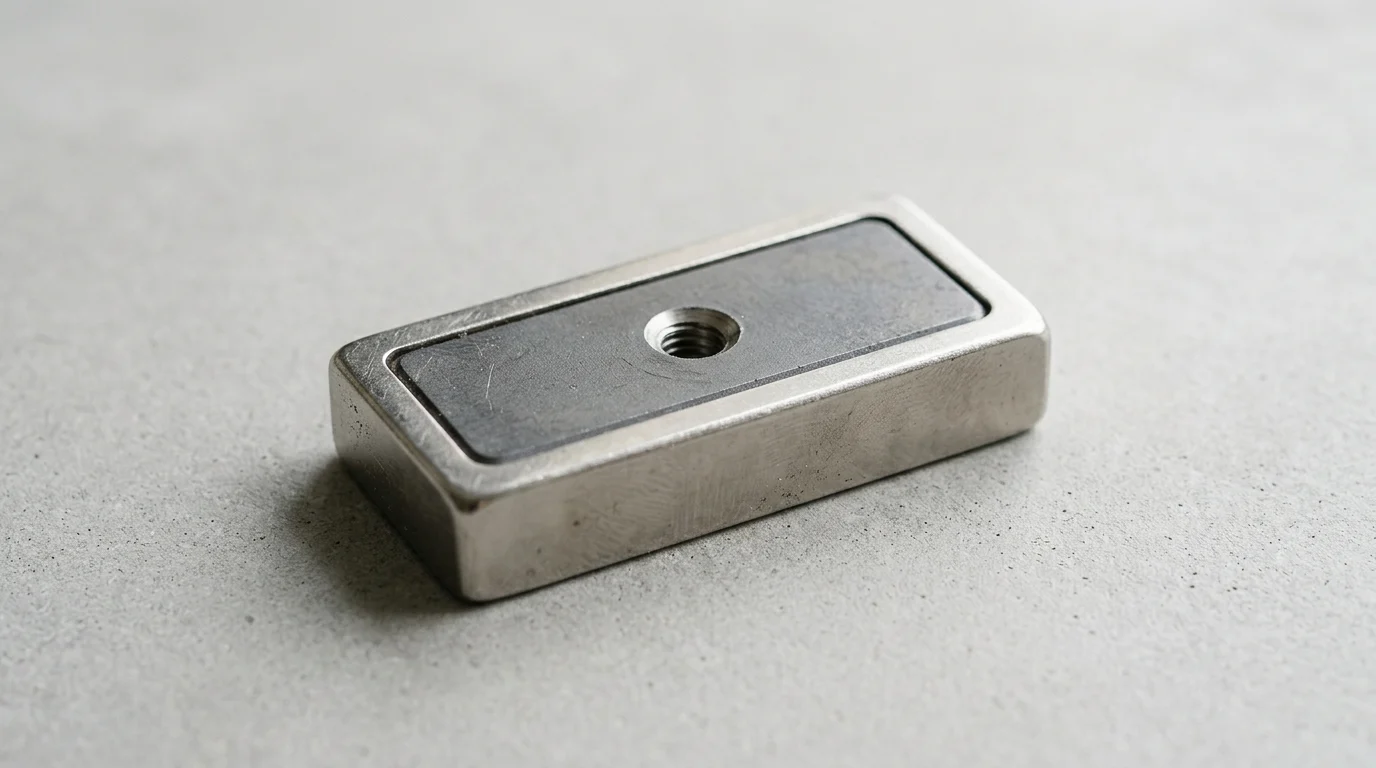
A rectangular pot magnet can deliver impressive holding power, but its real performance is decided long before it touches the workpiece. In clamping, fixturing, conveyors, and robotic handling, the mounting interface determines whether the magnet achieves near-rated pull force or loses strength through air gaps, tilt, vibration, and poor load transfer. Even a small misalignment can turn a high-strength magnetic assembly into a reliability risk, especially when heavy parts or repetitive cycles are involved. This article explains how mounting choices influence magnetic contact, mechanical stability, safety margins, and service life—so engineers and buyers can specify rectangular pot magnets that perform predictably in demanding industrial environments.
Why Rectangular Pot Magnet Mounting Matters
A Rectangular Pot Magnet represents a highly efficient magnetic assembly designed for industrial clamping, fixturing, and heavy-duty mounting. Unlike raw magnets, these assemblies integrate a highly coercive magnetic core within a specifically engineered steel channel. This design not only protects the brittle magnetic material from physical impact but also alters the magnetic circuit, focusing the flux lines onto a single active face to maximize holding power.
However, the intrinsic magnetic strength of the assembly is only one part of the performance equation. The method chosen to mount the magnet to a host structure fundamentally determines how effectively that magnetic power translates into practical mechanical stability. Proper mounting techniques ensure that the magnet maintains optimal contact with the target surface, whereas improper mounting can introduce mechanical stress, unintended air gaps, or leverage points that drastically degrade performance. In industrial applications where a single assembly may be rated for a 50 kg direct pull force, an inadequate mounting method can reduce the effective holding capacity by up to 40% to 60%, leading to catastrophic operational failures.
How mounting affects holding force
The holding force of a magnetic assembly relies heavily on maintaining a closed, flush magnetic circuit with the target substrate. When a magnet is mounted rigidly without accounting for the surface variations of the target, slight angular deviations or tilts can occur. Because magnetic force decays steeply and is highly geometry-dependent when interacting with ferrous surfaces, even a microscopic tilt introduced by an uneven mounting bracket can create an unintended air gap. A mounting method that allows for slight articulation or utilizes precision-machined flush hardware ensures that the active face of the magnet sits perfectly flat against the ferrous target.
Furthermore, the mounting hardware dictates how the load is distributed across the magnetic assembly. Fasteners that are torqued unevenly can warp the steel housing, subtly pulling the magnetic core away from the active plane. Conversely, a correctly specified mounting setup—whether through precision countersunk screws or precisely tensioned threaded studs—ensures that the load is transferred cleanly through the steel housing rather than placing shear stress directly on the fragile magnetic core. This mechanical harmony allows the assembly to achieve 100% of its rated pull force under ideal conditions.
Commercial risks of poor mounting
Failing to optimize the mounting method carries significant commercial and operational risks. The most immediate consequence is the physical dropping of suspended payloads. If an automated robotic arm or an overhead conveyor system utilizes rectangular magnetic assemblies to lift 100 kg (220 lb) steel components, a failure in the mounting interface—such as a screw backing out due to vibration or a rigid mount causing peeling—can result in dropped loads, damaged inventory, and severe workplace safety hazards.
Beyond immediate safety concerns, poor mounting leads to accelerated wear and increased lifecycle costs. If mounting hardware allows the magnet to rattle or shift against the target surface, the resulting friction will quickly degrade the protective nickel-copper-nickel (NiCuNi) plating, which is typically only 10 to 20 microns thick. Once the plating is breached, the internal Neodymium core is exposed to moisture, leading to rapid oxidation, swelling, and eventual demagnetization. This necessitates premature replacement cycles, driving up maintenance budgets and causing unacceptable downtime in continuous manufacturing environments.
What a Rectangular Pot Magnet Is

To understand how mounting impacts performance, it is necessary to examine the anatomical structure of the assembly itself. A rectangular pot magnet is not a single homogenous block of magnetic material; rather, it is a composite component engineered to manipulate magnetic fields for industrial advantage. The fundamental principle relies on encasing a raw permanent magnet—typically Sintered Neodymium (NdFeB) or Ceramic Ferrite—inside a precisely dimensioned steel enclosure.
This enclosure serves a dual purpose: mechanical protection and magnetic amplification. By surrounding the magnet on three sides, the steel housing acts as a flux conductor. It redirects the magnetic field lines that would normally emit from the sides and back of the magnet, channeling them strictly toward the open, active face. This flux-focusing phenomenon can increase the effective pull force of the assembly by 30% to 50% compared to a raw magnet of identical volume, making it highly efficient for space-constrained engineering applications.
Steel channel, magnetic core, and housing design
The steel channel is typically manufactured from low-carbon steel, chosen for its high magnetic permeability and structural formability. The internal magnetic core is bonded into this channel using high-strength industrial adhesives. The geometry of the housing dictates the available mounting options; for example, standard rectangular assemblies often feature stamped or machined holes that align with the gaps in the magnetic core, allowing fasteners to pass through without disrupting the primary magnetic circuit.
Housing designs vary significantly based on the intended application. For instance, a Square Shell Magnet utilizes specialized housing that often incorporates a durable polymer or rubberized coating over the steel and magnet. This specific design protects delicate target surfaces from scratches while simultaneously increasing the coefficient of friction, which is vital for resisting shear forces. The exact dimensions of the steel channel, which frequently range from compact 20mm lengths to robust 120mm x 50mm blocks, dictate the size and type of fasteners that can be safely integrated into the design.
Application conditions that affect performance
The physical environment in which the magnet operates dictates the performance baseline and heavily influences the required housing specifications. Temperature is a primary constraint. Standard N35 grade Neodymium magnets suffer irreversible flux loss if operating temperatures exceed 80°C (176°F). If the application involves high heat—such as in plastic injection molding fixtures or automotive welding jigs—the assembly must utilize high-coercivity grades (e.g., N35SH or N40UH) capable of withstanding up to 150°C, and the housing adhesives must be rated for equivalent thermal loads.
Moisture and chemical exposure also threaten the integrity of the assembly. While the steel channel provides structural rigidity, both the steel and the Neodymium core are highly susceptible to oxidation. Standard assemblies rely on triple-layer NiCuNi electroplating, but in marine or heavy washdown environments, the housing may require additional encapsulation in stainless steel or thick epoxy potting. The chosen mounting method must not compromise these protective layers; for example, overtightening a metal screw can crack the epoxy seal, allowing moisture ingress and drastically reducing the operational lifespan of the unit.
Common Rectangular Pot Magnet Mounting Methods
The versatility of rectangular magnetic assemblies stems largely from the variety of standardized mounting interfaces engineered into their steel housings. Selecting the correct mechanical interface is essential for integrating the magnet into larger frameworks, brackets, or automated machinery. Each mounting method offers distinct advantages in terms of load distribution, space efficiency, and ease of installation.
Engineers must evaluate the specific mechanical demands of their system—such as the direction of the applied load, the thickness of the mating bracket, and the availability of tools in the field—to select the optimal configuration. The three most prevalent mounting methods include countersunk holes, threaded studs, and internal threaded sockets.
Countersunk holes, threaded studs, and internal threads
Countersunk holes are one of the most common and versatile mounting configurations. A Rectangular Countersunk Magnet features one or more precisely machined conical recesses that allow flathead screws (typically M3, M4, or M6) to sit completely flush with or slightly below the active magnetic surface. This flush profile is critical because any protruding screw head would introduce an air gap, severely degrading the holding force.
Threaded studs feature a male threaded bolt protruding from the back (non-magnetic side) of the steel channel. This allows the magnet to be passed through a hole in a mounting bracket and secured from behind with a nut and washer. Internal threads, conversely, feature a tapped female hole or a welded threaded boss on the back of the assembly, accepting standard bolts (e.g., M6, M8, or M10). Both threaded configurations are preferred for heavy-duty applications because they completely isolate the fastening hardware from the active magnetic face, eliminating the risk of surface interference.
| Mounting Method | Fastener Compatibility | Typical Shear Load Retention | Best Application |
|---|---|---|---|
| Countersunk Hole | M3 to M6 Flathead Screws | 15% - 25% of Direct Pull | Flush surface requirements, light to medium duty |
| Threaded Stud | M4 to M8 Nuts | 20% - 25% of Direct Pull | Through-hole bracket mounting, rapid assembly |
| Internal Thread | M4 to M10 Bolts | 20% - 25% of Direct Pull | Blind hole applications, heavy machinery fixtures |
Pull direction and load comparison
The orientation of the load relative to the magnetic face drastically alters the effective holding capacity. Direct pull force—often referred to as the rated holding force—is measured when the load is applied perfectly perpendicular to the magnet's active face. Under these ideal conditions, the full concentrated flux of the steel channel is utilized. However, in many real-world applications, the load is applied parallel to the surface, resulting in shear force.
Because the magnetic flux does not actively resist lateral sliding, shear resistance is highly dependent on the coefficient of friction between the magnet and the target substrate. While dry, rough steel-on-steel friction can be higher, the effective friction coefficient for smooth, coated, or slightly lubricated industrial surfaces often drops significantly. Consequently, a magnet rated for 100 kg of direct pull will typically begin to slide under a shear load of just 15 to 25 kg. Mounting methods that incorporate mechanical interlocking, structural ledges, shrouds, or friction-enhancing rubber coatings are required to provide reliable shear resistance, as they offer far more stability than friction alone.
Horizontal, vertical, and recessed mounting
Horizontal mounting (where the magnet faces downward to lift or suspend a load) relies entirely on the direct pull capacity. In this orientation, the mounting hardware must withstand the full gravitational pull of the suspended mass. Vertical mounting (where the magnet attaches to a wall or vertical bulkhead) introduces continuous shear stress. In these setups, engineers often employ multiple rectangular magnets spread across a wide bracket to distribute the shear load and prevent rotational peeling.
Recessed mounting is an advanced technique where the rectangular magnet is embedded into a milled pocket within the primary tool or fixture. This method protects the magnet from lateral impacts and abrasive wear. However, recessed mounting requires exacting machining tolerances. A typical design specification requires a +0.5mm clearance around the perimeter of the magnet to accommodate thermal expansion and manufacturing variances, ensuring the magnet does not become wedged or structurally stressed within the pocket.
Key Factors That Affect Holding Performance
Achieving the theoretical maximum holding force of a magnetic assembly is rarely possible in field conditions. The rated specifications provided by manufacturers are typically generated in controlled laboratory environments using thick, perfectly flat, low-carbon steel test plates. In practice, if the target substrate is too thin to absorb the full magnetic flux (reaching magnetic saturation), or if it consists of less permeable materials like 300-series stainless steel, the holding force will drop dramatically regardless of the mounting method.
Understanding these subtractive factors is crucial for specifying the correct magnet size and mounting technique. Engineers must apply appropriate safety factors—often over-specifying the rated pull force by 200% to 300%—to ensure reliable operation once environmental and mechanical realities are factored into the design.
Air gap, surface flatness, and coating thickness
The most critical factor affecting magnetic performance is the air gap between the active face of the magnet and the target substrate. Because magnetic force diminishes steeply as distance increases, even microscopic barriers have a profound impact. An air gap of just 1.0mm can reduce the effective pull force of a standard Neodymium rectangular assembly by over 50%.
This air gap is not always empty space; it frequently consists of paint, powder coating, rust, or uneven substrate topography. A standard industrial powder coating layer of 50 to 100 microns creates a permanent, unavoidable air gap. Furthermore, if the target surface is convex, concave, or deeply pitted, the rigid, flat face of the rectangular magnet cannot make flush contact. In such cases, a mounting method that allows the magnet to pivot slightly on a central threaded stud can help the assembly align itself optimally against the uneven surface, minimizing the average air gap.
Torque, fastener preload, and bracket stiffness
The mechanical installation of the magnet itself introduces stress factors. When utilizing countersunk mounting holes, the torque applied to the fastening screw must be strictly controlled. The Neodymium material inside the steel channel is highly brittle, akin to ceramic. If an M4 flathead screw is over-torqued beyond its recommended limit (typically around 2.0 to 2.5 Nm for standard assemblies), the outward pressure of the conical screw head can fracture the magnet, instantly degrading its structural and magnetic integrity.
The stiffness of the mounting bracket also plays a vital role. If a rectangular magnet is bolted to a thin, flexible sheet metal bracket, any load applied to the system may cause the bracket to flex. This flexion applies uneven leverage to the magnet, causing one edge to lift away from the target surface. This "peeling" action rapidly breaks the magnetic circuit, causing the assembly to detach at a fraction of its rated load capacity. Utilizing rigid, heavily gusseted brackets ensures that the load remains distributed evenly across the entire magnetic face.
Temperature, corrosion, and shock loading
Environmental extremes dictate both the choice of magnet grade and the robustness of the mounting hardware. As ambient temperatures rise, the kinetic energy within the Neodymium core increases, temporarily reducing the net magnetic flux. If the temperature exceeds the specific grade's Maximum Operating Temperature, the magnet will suffer permanent demagnetization. The mounting hardware must also account for thermal expansion; mismatched expansion coefficients between a steel bracket, a stainless steel screw, and the magnet housing can induce severe mechanical stress.
Corrosion and shock loading further complicate performance. In environments with high vibration—such as heavy stamping presses or mobile transit applications—the repeated shock loading can cause standard threaded fasteners to back out. The use of chemical threadlockers or mechanical locking washers is mandatory in these scenarios to maintain the necessary preload on the mounting hardware. Additionally, any damage to the 10-20 micron NiCuNi protective plating during the mounting process will invite galvanic corrosion, rapidly degrading the internal magnetic core and causing the assembly to fail mechanically from the inside out.
How to Select the Best Mounting Method
Selecting the ideal mounting method for a rectangular pot magnet requires a systematic approach that balances mechanical strength, environmental durability, and operational practicality. There is no single universal solution; the optimal choice depends entirely on the specific constraints of the end-use application.
Procurement teams and design engineers must collaborate to evaluate the load cases, lifecycle requirements, and maintenance protocols of the equipment being designed. By matching the mounting style to the physical realities of the workspace, organizations can maximize the return on investment for their magnetic hardware while ensuring strict adherence to safety standards.
Match load case, substrate, and environment
The first step in selection is mapping the exact load case. If the application involves suspending heavy loads vertically (direct pull), internal threaded sockets or heavy-duty threaded studs provide the necessary tensile strength, as the load is borne entirely by the robust steel housing and the bolt threads. If the application involves significant shear forces, the design must incorporate mechanical stops, ledges, shrouds, or friction-enhancing rubber coatings, regardless of the core mounting method chosen.
The nature of the substrate and the surrounding environment also dictate the mounting choice. For instance, if the magnet is being mounted into a blind hole on a thick aluminum fixture plate, an internal threaded magnet secured from behind with a precisely measured bolt is ideal. Conversely, if the environment involves heavy chemical washdowns, utilizing a fully enclosed threaded stud design minimizes the number of exposed seams and crevices where corrosive agents can pool, thereby extending the lifespan of the assembly.
Choose between pull force, safety, and serviceability
Engineers must frequently navigate trade-offs between absolute pull force, operator safety, and field serviceability. While a rigidly bolted internal-thread magnet provides the highest ultimate holding force, it may be difficult to remove or replace in the field if it becomes damaged. In applications where the magnet is considered a wear item—such as in abrasive material handling— countersunk magnets offer superior serviceability, allowing technicians to swap out damaged units rapidly using basic hand tools.
| Selection Criterion | Priority Focus | Recommended Mounting Style | Typical Industrial Application |
|---|---|---|---|
| Maximum Holding Force | Direct Pull perpendicular to surface | Internal Thread (Heavy Duty) | Heavy machinery, lifting fixtures |
| Operator Safety | Minimizing shear/sliding risks | Recessed Mounting with Mechanical Stops | Automated robotic arms |
| Field Serviceability | Rapid replacement, minimal tools | Countersunk Screws | Abrasive material handling |
| Environmental Protection | High corrosion/moisture resistance | Fully Enclosed Threaded Stud | Marine or chemical washdown |
Validate quality before procurement
Before committing to a large-scale integration, it is imperative to validate the quality and consistency of the magnetic assemblies. Ensuring that the manufacturer adheres to strict quality control standards for critical dimensions and magnetic flux consistency prevents costly assembly line disruptions and guarantees that the selected mounting hardware interfaces perfectly with the housing.
Thorough prototyping should involve testing the assemblies with the exact mounting hardware and target substrates that will be used in production. This physical validation confirms that the chosen fasteners do not over-stress the housing, that the air gaps are within acceptable tolerances, and that the final pull force meets the required safety factors. By meticulously aligning the mechanical mounting strategy with the capabilities of a high-quality Rectangular Pot Magnet , engineers can ensure reliable, long-term performance in even the most demanding industrial environments.
Further reading:
Key Takeaways
- Select a mounting method that keeps the active magnetic face fully flush with the ferrous target to preserve the rated pull force.
- Avoid unintended air gaps, tilt, and peeling loads because they can reduce effective holding capacity by 40% to 60% in industrial applications.
- Use precision countersunk screws, threaded studs, or properly machined brackets to transfer load through the steel housing rather than the brittle magnetic core.
- Torque fasteners evenly to prevent housing distortion, uneven contact, and premature wear in high-duty clamping or lifting systems.
- Design for the real load direction, because shear, vibration, and leverage can produce far lower practical holding strength than a direct-pull rating.
Frequently Asked Questions
Why does mounting method affect a rectangular pot magnet’s holding force?
Holding force depends on flush contact with the ferrous surface. Poor mounting can create tilt, air gaps, or uneven load transfer, which reduces the closed magnetic circuit and can significantly lower real-world pull strength.
How much holding capacity can be lost from improper mounting?
In demanding industrial setups, inadequate mounting can reduce effective holding capacity by 40% to 60%, especially when air gaps, vibration, peeling forces, or misalignment are introduced.
What is the best way to mount a rectangular pot magnet?
The best method depends on the application, but precision-machined flush hardware, correctly torqued fasteners, and mounts that allow full face contact generally deliver the most reliable performance.
Do rectangular pot magnets work the same in shear as in direct pull?
No. Rated holding force is usually based on direct pull under ideal contact conditions. Shear, sliding, vibration, or peeling forces can reduce practical holding strength and should be considered in the mounting design.
Can overtightening screws damage a rectangular pot magnet?
Yes. Uneven or excessive torque can distort the steel housing or stress the internal magnet, reducing contact quality and potentially shortening service life.