 EN
EN AR
AR HR
HR CS
CS DA
DA NL
NL FI
FI FR
FR DE
DE EL
EL IT
IT JA
JA KO
KO NO
NO PL
PL PT
PT RU
RU ES
ES SV
SV IW
IW VI
VI TH
TH TR
TR FA
FA MS
MS
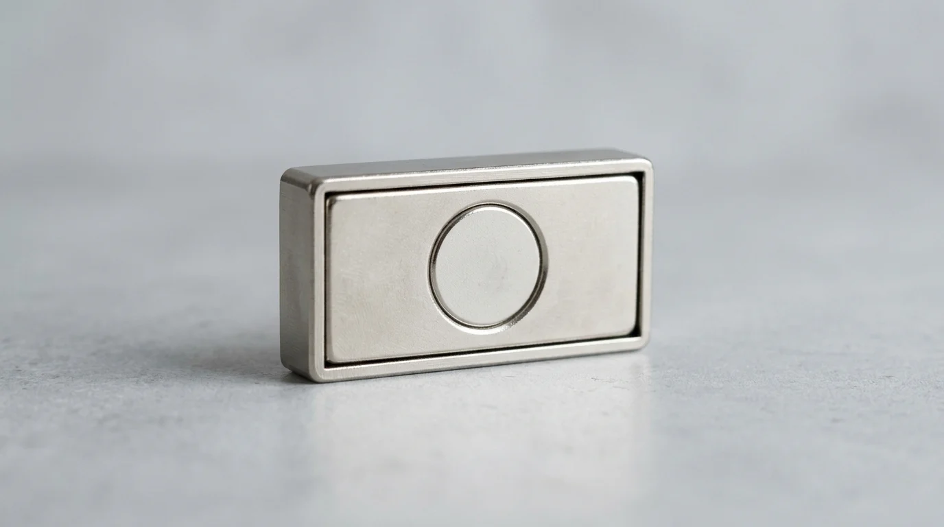
In factories where cycle time, repeatability, and tool access matter, fastening every steel component with clamps or bolts can slow production. Rectangular pot magnets give engineers a compact alternative: strong, reusable holding force concentrated on one active face and shaped for rails, channels, jigs, and robotic tooling. Their linear geometry helps distribute load, align sheet metal, and reduce twisting in applications where round magnets are less efficient. This article explains how these magnetic assemblies work, why their steel housing improves performance, and what engineers should consider when selecting them for welding fixtures, material handling, and automated manufacturing systems.
Why Rectangular Pot Magnets Matter in Engineering
In modern manufacturing and industrial engineering, securing components efficiently without permanent mechanical fastening is a persistent challenge. Engineers frequently turn to magnetic assemblies to provide temporary holding, fixturing, and clamping forces. Among these solutions, rectangular pot magnets have emerged as a highly specialized and effective tool. Unlike standard bare magnets, which distribute their magnetic field symmetrically in all directions, pot magnets encase the magnetic material within a steel housing. This housing alters the magnetic circuit, concentrating the flux onto a single active face and dramatically amplifying the holding force.
While round pot magnets are ubiquitous, their circular footprint is not always optimal for linear applications or tight dimensional constraints. Rectangular variants offer a flush, linear profile that aligns perfectly with structural channels, conveyor rails, and robotic end-effectors. Depending on the size and internal magnetic material, these assemblies can deliver holding forces ranging from a modest 5 kg up to heavy-duty industrial capacities exceeding 150 kg per unit. By maximizing the contact area along a straight edge, engineers can achieve superior load distribution and prevent the rotational slippage that sometimes plagues single-point circular magnets.
Key selection factors
Selecting the appropriate magnetic assembly requires a thorough analysis of the physical constraints and operational demands of the application. The primary advantage of a rectangular form factor is its ability to maximize magnetic contact area within narrow spaces. Engineers must evaluate the channel width-to-length ratio; ratios of 3:1 or 4:1 are standard in the industry, as they optimize linear holding capacity without requiring excessively wide mounting surfaces.
Another critical selection factor is the direction of the applied load. Magnets are inherently strongest when resisting direct, perpendicular pull-off forces. However, in many vertical mounting scenarios, the magnet must resist shear forces—gravity pulling the load downward across the face of the magnet. Because the coefficient of friction between a steel housing and a steel workpiece is relatively low (often around 0.15 to 0.25), a rectangular assembly can be oriented horizontally to provide a wider base of resistance against shear, or integrated with mechanical stops to bear the sheer weight while the magnet provides the clamping force.
Common manufacturing use cases
The linear geometry of these magnets makes them indispensable across a variety of specialized manufacturing environments. In automated welding and fabrication, they are frequently used in custom jigs and fixtures to hold steel plates at precise 90-degree angles before tack welding. Their narrow profile allows them to be embedded directly into the walls of the fixture, leaving the joint area completely unobstructed for the welding torch.
In material handling, automation engineers utilize a Rectangular Pot Magnet on robotic arms to pick and place sheet metal blanks. The straight edges of the magnet align flush with the edges of the sheet metal, ensuring consistent orientation during high-speed transfers. Furthermore, in the woodworking and cabinetry industries, these magnets are routinely embedded into door frames and access panels, providing a low-profile, high-strength closure mechanism that withstands thousands of actuation cycles without mechanical wear.
How Rectangular Pot Magnets Work

To properly integrate magnetic holding into a production line, engineers must understand the underlying physics of the magnetic circuit. A standard bare magnet has a north and a south pole, with magnetic flux lines traveling through the surrounding air from one pole to the other. Air is a poor conductor of magnetic flux, leading to a highly dispersed field that is effective over a distance but lacks concentrated holding power at the surface.
Rectangular pot magnets solve this inefficiency by utilizing a ferromagnetic steel shell—typically a U-channel or a rectangular cup. This steel housing acts as a highly permeable conduit for the magnetic flux. It captures the flux from the internal magnet's back and sides and redirects it to the front face. As a result, both the north and south poles are effectively presented at the active surface. This flux concentration can increase the surface pull force by up to 300% compared to a bare magnet of the exact same volume and grade, making it an incredibly efficient use of magnetic material.
Basic structure and function
The basic structure consists of three main components: the steel housing, the permanent magnet insert, and an isolating material such as epoxy resin. The magnet is seated inside the steel channel, but it is crucial that the sides of the magnet do not make direct physical contact with the steel walls. If they did, the flux would short-circuit internally, drastically reducing the external holding power.
To prevent this, the gap between the magnet and the steel housing is filled with a non-magnetic potting material, usually a high-strength industrial epoxy. This epoxy serves a dual purpose: it maintains the precise air gap required to force the magnetic flux out through the front face, and it locks the brittle magnet securely in place, protecting it from mechanical impacts and environmental contaminants.
Core design elements
Several core design elements dictate the performance and durability of the assembly. The thickness of the steel housing is paramount. If the steel is too thin, it will reach magnetic saturation and leak flux out the back and sides, wasting potential holding power. Engineers typically specify housing thicknesses ranging from 1.5 mm to 3.0 mm, depending on the strength of the internal magnet, to ensure the steel can carry the full magnetic load.
Mounting features are another critical element. Because the steel housing provides a machinable exterior (unlike the brittle magnet itself), it can be drilled, tapped, or stamped. A common configuration is the Rectangular Countersunk Magnet , which features pre-drilled holes that allow standard flat-head screws to sit flush with or slightly below the magnetic surface. This ensures that the fastener does not interfere with the target material, maintaining the zero-gap contact necessary for maximum holding force.
Material options: neodymium, ferrite, and others
The choice of internal magnetic material fundamentally alters the assembly's performance metrics, cost, and environmental resilience. Neodymium (NdFeB) is the most powerful option, offering the highest energy product (typically N35 to N52 grades). It is ideal for compact spaces requiring immense strength, though standard grades are limited to maximum operating temperatures of 80°C, with specialized high-temp grades pushing this to 150°C or 200°C.
Ferrite (ceramic) magnets offer a cost-effective alternative for larger footprint applications. While they possess only about one-tenth the pull force of Neodymium by volume, they boast excellent corrosion resistance and can operate at temperatures up to 250°C without significant demagnetization. For extreme environments, Samarium Cobalt (SmCo) is sometimes used, offering near-Neodymium strength with temperature stability up to 350°C, albeit at a premium price point.
| Material Type | Relative Pull Force | Max Operating Temp (°C) | Corrosion Resistance | Relative Cost |
|---|---|---|---|---|
| Neodymium (NdFeB) | Very High | 80 - 200 | Low (Requires Coating) | High |
| Ferrite (Ceramic) | Low | 250 | Excellent | Low |
| Samarium Cobalt (SmCo) | High | 250 - 350 | Good | Very High |
Key Specifications to Compare
When specifying rectangular pot magnets for industrial applications, engineers cannot rely solely on the theoretical maximum pull force listed in a catalog. Theoretical values are calculated under ideal laboratory conditions: a perfectly flat, thick, low-carbon steel test plate with zero air gap and a perpendicular pull. Real-world manufacturing environments rarely meet these conditions.
To prevent catastrophic failures, particularly in overhead lifting or heavy fixturing, engineers must apply rigorous safety factors. A standard safety factor of 3:1 is recommended for horizontal holding applications, while a 4:1 or even 5:1 safety factor is mandatory for overhead or sheer-load applications. This means if a load weighs 10 kg, the specified magnet must have a rated pull force of at least 40 kg to 50 kg to account for dynamic loads, vibrations, and suboptimal surface conditions.
Pull force and air gap performance
The most significant variable affecting magnetic performance is the air gap. In magnetic terms, an air gap is any non-magnetic material existing between the magnet's active face and the steel target. This includes actual air, but also paint, powder coating, rust, oil, dust, and even uneven surface textures on the workpiece.
Because the magnetic circuit of a pot magnet is highly optimized to keep flux lines close to the surface, its performance degrades exponentially as the air gap increases. For a standard Neodymium rectangular pot magnet , introducing a mere 1.0 mm air gap (such as a thick layer of industrial paint) can reduce the effective holding force by 50% to 70%. Engineers must measure the expected coating thicknesses on their workpieces and consult the manufacturer's air gap vs. pull force curves to select an appropriately oversized magnet.
Dimensions and mounting options
Dimensional constraints often dictate the specific mounting style chosen. Rectangular assemblies are defined by their length, width, and height (thickness). A lower profile (height) is generally preferred to minimize interference in tight assemblies, but a minimum height is required to house a magnet thick enough to generate the desired force.
Mounting options vary widely to accommodate different structural designs. Beyond standard countersunk holes , engineers may utilize a Flanged Rectangular Magnet , which extends the steel housing past the magnetic core to create mounting tabs . This allows the magnet to be bolted down onto a surface without drilling through the magnetic field area, preserving the maximum possible active face for holding the target object.
Comparison table for magnet types
To illustrate the relationship between physical dimensions, mounting styles, and resulting pull forces, it is helpful to compare standard configurations. The table below demonstrates how varying the length and the internal material impacts the overall holding capacity and the intended mounting method.
| Dimensions (L x W x H) mm | Material | Mounting Type | Rated Pull Force (N) | Rated Pull Force (kg) |
|---|---|---|---|---|
| 120 x 15 x 6 | Neodymium | 2x Countersunk (M4) | 294 N | 30 kg |
| 120 x 15 x 6 | Ferrite | 2x Countersunk (M4) | 49 N | 5 kg |
| 200 x 20 x 10 | Neodymium | Flanged (M5 holes) | 784 N | 80 kg |
| 50 x 10 x 5 | Neodymium | Threaded Stud (M3) | 98 N | 10 kg |
This comparison highlights the massive performance discrepancy between Neodymium and Ferrite within the exact same dimensional footprint. It also shows how longer assemblies (e.g., 200 mm) scale up in force, providing a broad linear grip ideal for stabilizing long rails or sheet metal edges.
Practical Applications in Production
Transitioning from theoretical specifications to practical implementation requires a deep understanding of production line dynamics. In high-volume manufacturing, minimizing cycle time is a constant priority. Traditional mechanical clamps, toggles, and bolts require operators to perform multiple manual motions per part, adding seconds to every cycle.
By replacing mechanical fasteners with rectangular pot magnets in non-critical holding areas, manufacturers can achieve significant efficiency gains. Time-motion studies in assembly environments have shown that magnetic fixturing can reduce part loading and unloading cycle times by up to 15% to 20%. The operator simply places the steel component against the magnetic datum surface, and it instantly locks into the correct orientation, ready for the next automated or manual process.
Specification process for engineers
When an engineer is tasked with integrating a magnetic hold-down system, they follow a strict specification process. First, the total mass and dynamic load of the workpiece are calculated. Second, the orientation of the load is assessed to determine if the magnet will face a direct pull (perpendicular) or a shear slip (parallel).
This distinction is vital because the shear force resistance of a pot magnet is typically only 20% to 30% of its direct pull force rating. If a magnet is rated for 100 kg of direct pull, it will likely begin to slide down a vertical steel wall under a load of just 20 kg to 30 kg. Third, the worst-case air gap is calculated based on maximum allowable paint and dirt accumulation. Finally, the engineer selects a magnet that meets these derated calculations while fitting within the available CAD envelope.
Magnetic holding vs mechanical clamping
The debate between magnetic holding and mechanical clamping is a common one in tool design. Magnetic holding excels in applications where marring or deforming the workpiece is unacceptable. Because the magnetic force is distributed evenly across the rectangular face, it does not create the localized pinch points or stress fractures associated with heavy mechanical clamp jaws.
However, mechanical clamping remains superior for applications involving high-vibration machining (like heavy CNC milling) or where the workpiece is non-ferrous (aluminum, plastics). In many modern fixtures, a hybrid approach is used: rectangular pot magnets provide rapid, temporary location and light holding of the part, while automated hydraulic clamps engage subsequently to secure the part for heavy machining operations.
Common failure modes
Despite their robust steel housings, magnetic assemblies are not immune to failure if misapplied. Thermal demagnetization is the most common failure mode. Standard Neodymium (N35 grade) loses approximately 0.11% of its flux density for every degree Celsius it is heated above ambient temperature. If it exceeds its maximum operating temperature (typically 80°C), the demagnetization becomes irreversible, permanently ruining the tool.
Another frequent failure mode is epoxy degradation. In environments with harsh chemical solvents or continuous exposure to synthetic cutting fluids, the potting epoxy can become brittle and crack. This allows moisture to penetrate the housing, leading to rapid oxidation and swelling of the Neodymium magnet, which eventually shatters the assembly from the inside out. Specifying chemically resistant resins or fully welded stainless-steel enclosures is necessary for these aggressive environments.
Sourcing, Compliance, and Final Selection
The final stage of deploying rectangular pot magnets involves navigating the supply chain, ensuring quality control, and meeting international compliance standards. As magnetic assemblies are often critical to the safety of lifting equipment and the precision of automated machinery, sourcing them from unverified vendors carries significant risk.
In global manufacturing, consistency is just as important as peak performance. A batch of magnets that varies wildly in pull force can cause unpredictable machine behavior, leading to dropped parts or jammed conveyors. Therefore, engineers and procurement teams must establish strict quality thresholds, often requiring defect rates to be maintained below 500 PPM (parts per million) for standard industrial applications, and even lower for automotive or aerospace integrations.
Supplier evaluation criteria
Evaluating a magnetic assembly supplier requires looking beyond the catalog specifications. Reputable suppliers should operate under ISO 9001 quality management systems and possess in-house magnetic testing capabilities. Engineers should request hysteresis graphs (B-H curves) for the raw magnetic material and pull-force test reports for the finished assemblies.
Logistics and scalability also play a crucial role. For custom rectangular sizes or specific mounting hole patterns, suppliers typically impose Minimum Order Quantities (MOQs). These MOQs generally range from 500 to 2,000 units depending on the complexity of the steel housing machining. Procurement teams must balance the cost savings of custom geometries against the lead times, which can span 4 to 8 weeks for specialized tooling and production.
Compliance and safety requirements
Compliance with environmental and safety regulations is non-negotiable. Magnets imported into Europe or North America must comply with RoHS (Restriction of Hazardous Substances) and REACH directives, ensuring that the protective platings (such as nickel-copper-nickel) and the potting epoxies do not contain restricted heavy metals or toxic chemicals.
Furthermore, shipping powerful magnetic assemblies requires strict adherence to aviation safety standards. Under IATA (International Air Transport Association) Packing Instruction 953, the stray magnetic field emitted by a packaged shipment must be less than 0.00525 gauss when measured at a distance of 15 feet (4.6 meters). If the field exceeds this limit, it can interfere with aircraft navigation instruments, and the shipment will be classified as Dangerous Goods, incurring significant freight delays and surcharges. Proper magnetic shielding using steel-lined packaging is essential.
Decision checklist
Before issuing a final purchase order, engineering and purchasing teams should review a comprehensive decision checklist. First, verify the maximum operating temperature of the production environment against the magnet's thermal rating. Second, confirm the safety factor matches the load orientation (direct vs. shear) and accounts for the worst-case air gap.
Third, ensure the mounting method (countersunk, threaded, or flanged) is compatible with the fixture's material thickness and assembly process. Finally, validate the supplier's testing protocols and compliance certifications. By methodically addressing these mechanical, environmental, and logistical parameters, engineers can successfully leverage rectangular pot magnets to create safer, faster, and more reliable manufacturing processes.
Further reading:
Key Takeaways
- Use rectangular pot magnets when a linear footprint must fit narrow channels, conveyor rails, welding fixtures, or robotic tooling.
- Select the magnet size and material based on the required holding force, which may range from about 5 kg to more than 150 kg per unit.
- Evaluate the load direction early because magnetic holding is strongest in direct pull-off and weaker in shear due to typical steel-on-steel friction of about 0.15 to 0.25.
- Add mechanical stops in vertical or high-shear applications so the magnet provides clamping force while the stop carries the load.
- Choose rectangular assemblies for sheet metal handling when straight-edge alignment and reduced rotational slippage are more important than a compact circular footprint.
Frequently Asked Questions
What is a rectangular pot magnet used for in manufacturing?
It is used for temporary holding, fixturing, clamping, and pick-and-place tasks where a straight, low-profile magnetic contact area is more practical than a round magnet.
How does a rectangular pot magnet differ from a bare magnet?
A rectangular pot magnet is enclosed in a steel housing that concentrates magnetic flux on one active face, increasing holding force and improving control compared with an exposed magnet.
Why choose a rectangular shape instead of a round pot magnet?
Rectangular designs fit rails, channels, jigs, and robotic end-effectors more easily, while spreading load along a straight edge to reduce twisting and improve alignment.
What holding force can rectangular pot magnets provide?
Depending on size and magnetic material, holding forces can range from about 5 kg to more than 150 kg per unit under suitable contact conditions.
Are rectangular pot magnets effective against shear loads?
They are strongest against direct pull-off loads, not shear. For vertical mounting, engineers often add mechanical stops or design the fixture so the magnet clamps while another feature carries the weight.