 EN
EN AR
AR HR
HR CS
CS DA
DA NL
NL FI
FI FR
FR DE
DE EL
EL IT
IT JA
JA KO
KO NO
NO PL
PL PT
PT RU
RU ES
ES SV
SV IW
IW VI
VI TH
TH TR
TR FA
FA MS
MS
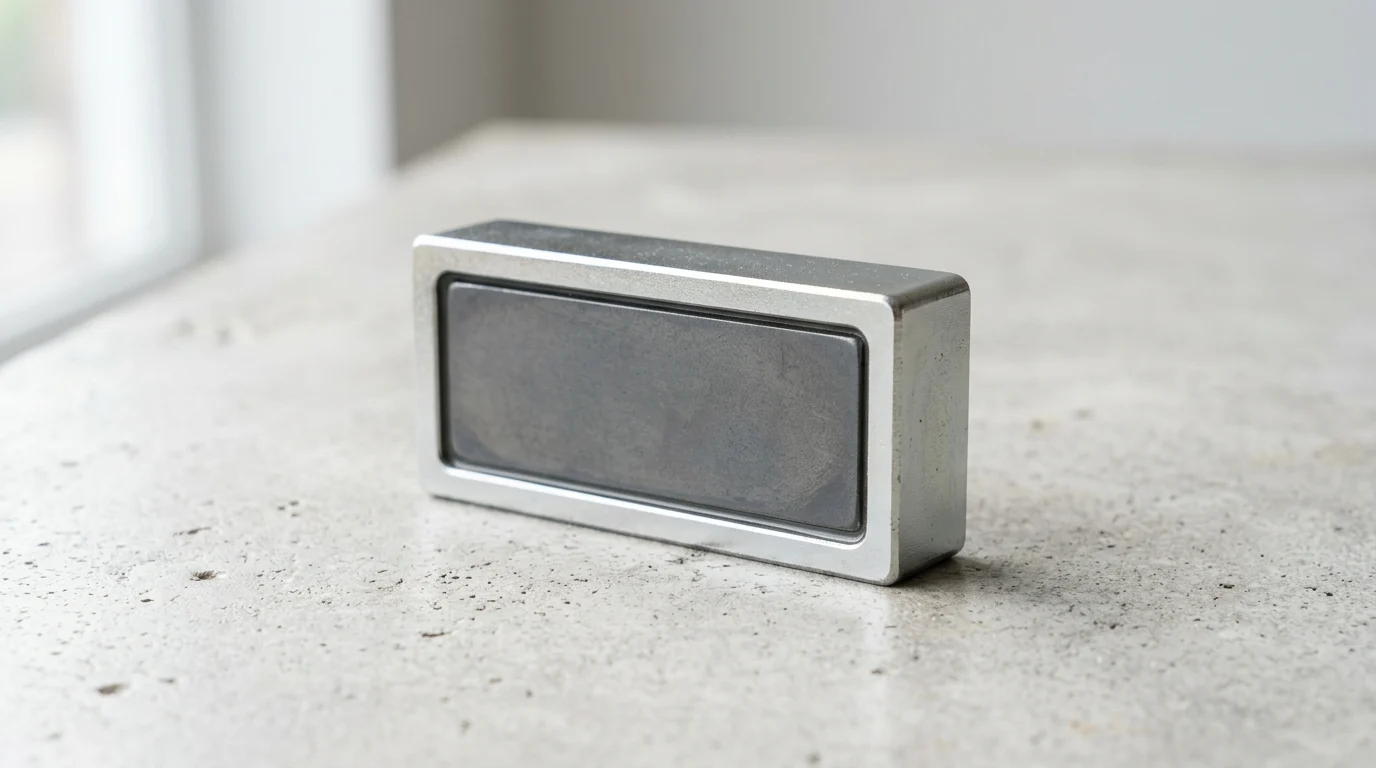
Industrial magnetic assemblies are often judged by a simple question: how much holding power can fit into the available space? A custom rectangular pot magnet answers that challenge by combining a high-strength magnetic core with a steel channel that concentrates flux onto one working face. For engineers and procurement teams, the details matter—dimensions, hole placement, magnet grade, coating, and load direction can all affect performance, cost, and lead time. This guide explains how rectangular pot magnets are specified, where they outperform round designs, what commercial factors influence manufacturing, and how to align a custom magnetic solution with real-world production requirements.
Define the Custom Rectangular Pot Magnet Project
Procuring magnetic assemblies for industrial applications requires moving beyond off-the-shelf solutions to highly tailored designs. A custom rectangular pot magnet consists of a powerful magnetic block—typically neodymium or ferrite—encased within a U-shaped steel channel. This steel housing is not merely protective; it actively alters the magnetic circuit, redirecting the magnetic flux lines to a single active face. This redirection can multiply the direct holding force by up to three times compared to a bare magnet of the same volume.
Engineers specify these assemblies when projects demand high holding forces confined to narrow tracks, slots, or linear profiles. Customization allows buyers to dictate exact dimensions—commonly ranging from 10mm to over 120mm in length—as well as specific mounting hole placements, magnetic grades, and protective coatings. By defining the project parameters accurately from the outset, procurement teams can align engineering requirements with manufacturing capabilities, ensuring structural reliability and cost-efficiency.
Industrial use cases and application goals
Industrial applications for rectangular magnetic assemblies are vast, spanning automation, cabinetry, material handling, and jig fixturing. In automated conveyor systems, these magnets frequently serve as non-contact sensors or holding mechanisms for metal pallets. Heavy-duty architectural applications utilize them for flush-mounted door catches or hidden architectural joints, where a 60mm by 15mm assembly can easily achieve over 30 kg of direct pull force.
The primary application goal is often maximizing holding power within a strictly limited footprint. Engineers must evaluate whether the magnet will face direct vertical pull, lateral sliding forces, or dynamic impacts. Defining these use cases early dictates the required steel thickness and the specific grade of the internal magnetic core, directly influencing the eventual tooling and production strategy.
Key commercial objectives
From a commercial perspective, custom magnetic assemblies aim to optimize the return on investment by eliminating the need to retrofit existing product housings. By ordering a custom dimension, manufacturers can standardize their own assembly lines, reducing labor time spent on complex mounting workarounds.
Cost barriers for custom runs have significantly decreased over the past decade. Minimum Order Quantities (MOQs) for custom designs typically range from 1,000 to 5,000 units, depending on the complexity of the steel stamping die. Furthermore, lead times for initial prototypes generally sit between 3 to 5 weeks, allowing companies to integrate custom magnetic solutions without derailing aggressive product launch schedules.
When rectangular pot magnets outperform round designs
While round magnetic bases are ubiquitous, they present distinct disadvantages in specific geometric integrations. Round assemblies are prone to spinning around a single central screw, whereas a Rectangular Pot Magnet provides inherent torsional resistance. The straight edges align perfectly within extruded aluminum channels, structural steel tracks, and cabinet corners, offering superior space utilization.
| Feature | Rectangular Pot Magnet | Round Pot Magnet |
|---|---|---|
| Mounting Profile | Flush alignment in linear channels and corners | Best for open, expansive flat surfaces |
| Torsional Resistance | High (two-point mounting prevents rotation) | Low (prone to spinning around a single screw) |
| Space Utilization | Excellent for narrow slots and edges | Suboptimal in linear tracks (leaves gaps) |
| Typical Pull Force Range | 5 kg to 150+ kg | 1 kg to 200+ kg |
This geometric advantage allows engineers to utilize two mounting points on a single linear magnet, entirely eliminating unwanted rotation during high-vibration applications. When installed in narrow recesses, the rectangular profile maximizes the volume of active magnetic material, delivering a stronger hold per square millimeter of available surface area.
Specify Performance Requirements

Translating application goals into a rigid technical specification is the most critical phase of the procurement process. A minor miscalculation in the magnetic grade, housing tolerance, or coating thickness can lead to premature failure in the field. Specifications must be documented in a comprehensive 2D or 3D CAD drawing that serves as the contractual baseline between the buyer and the manufacturer.
Performance requirements dictate not only the raw pulling power but also the assembly's survivability in its intended environment. Specifying exact parameters ensures that the manufacturer selects the correct raw materials and machining processes, preventing costly redesigns after the initial prototyping phase.
Magnet material, grade, and pull force
The core of the assembly is defined by its material and grade. Sintered Neodymium (NdFeB) is the industry standard for high-performance applications, available in grades ranging from N35 to N52. Upgrading from an N35 to an N52 core can increase the magnetic yield by approximately 20-30%, though it introduces a proportional increase in raw material costs.
Pull force is the primary metric of success, typically measured in kilograms or Newtons. It is critical to note that specified pull force is always measured under ideal conditions: a direct, perpendicular pull away from a flat, 10mm-thick low-carbon steel plate. If the application involves thinner sheet metal or painted surfaces, the actual holding force may drop by 40% to 60%, necessitating a higher-grade magnet to compensate.
Housing design, coating, and mounting holes
The U-channel housing is generally machined or stamped from A3 low-carbon steel, which offers excellent magnetic permeability. To prevent oxidation, the entire assembly requires a protective coating. The standard is a triple-layer Nickel-Copper-Nickel (Ni-Cu-Ni) plating, typically 15 to 20 microns thick. For outdoor or marine environments, epoxy or zinc coatings may be specified.
Mounting hole design directly dictates the installation hardware. A Counterbored Pot Magnet features a cylindrical flat-bottomed hole designed for socket head cap screws , ensuring the bolt head sits entirely below the magnetic surface. Conversely, a Rectangular Countersunk Magnet utilizes a conical hole to accommodate flat head machine screws . Specifying the correct angle (usually 90 or 100 degrees) prevents the screw from protruding and creating an air gap that would severely diminish the pull force.
Tolerance, temperature, corrosion, and shear load
Dimensional tolerances must be explicitly stated; standard machining offers ±0.1mm, while precision applications may require ±0.05mm. Temperature is another critical threshold. Standard N-series neodymium begins to suffer irreversible demagnetization above 80°C. For industrial motors or high-heat environments, high-temperature grades like SH (up to 150°C) or UH (up to 180°C) are mandatory.
Corrosion resistance is quantified via salt spray testing, with standard Ni-Cu-Ni surviving 24 to 48 hours, whereas specialized epoxy coatings can endure over 500 hours. Finally, buyers must account for shear load. When a magnet is mounted vertically on a wall, gravity exerts a sliding (shear) force. Due to the low friction of nickel plating against steel, the shear load capacity is typically only 15% to 25% of the direct pull force. A magnet rated for 100 kg of vertical pull may slide down a wall under just 20 kg of weight.
Compare Manufacturing Options
Understanding the manufacturing processes available allows buyers to optimize their designs for cost and structural integrity. The production of a custom magnetic assembly is a multi-stage process that merges traditional metalworking with advanced magnetic material handling. The choices made during this phase determine whether a product is viable for low-volume prototyping or high-volume mass production.
Manufacturers must balance the precision required by the steel housing with the fragile, brittle nature of the raw magnetic block. Selecting the right combination of housing fabrication, core material, and bonding agents is essential for long-term reliability.
Core production and assembly steps
The production of the steel U-channel generally falls into two categories: CNC milling and metal stamping. CNC machining is ideal for low-volume runs (under 1,000 units) or designs requiring exceptionally tight tolerances (±0.02mm) and complex counterbored geometries . However, CNC machining is comparatively slow and incurs higher per-unit costs.
For high-volume production, metal stamping is the preferred method. A custom stamping die, which may cost between $500 and $2,000 to produce, punches and folds the steel channel in a fraction of a second. Once the tooling cost is amortized, stamping can reduce the per-unit housing cost by up to 60%. Following the housing fabrication, the raw magnet block is magnetized, inserted into the channel, and secured before final plating or coating.
Sintered neodymium versus alternative materials
While sintered neodymium dominates the custom market due to its exceptional energy density (1.1 to 1.4 Tesla), alternative materials are highly relevant for specific environments. Hard ferrite magnets offer a much lower energy product (0.2 to 0.4 Tesla) but are virtually immune to corrosion and can operate at temperatures up to 250°C. Ferrite assemblies are often chosen for welding fixtures or low-cost consumer goods where size is not a constraint.
Samarium Cobalt (SmCo) is another alternative, bridging the gap between neodymium's strength and ferrite's temperature resistance. SmCo magnets can withstand temperatures exceeding 300°C without significant flux loss and possess excellent inherent corrosion resistance. However, SmCo is highly brittle and can cost three to five times more than standard NdFeB, limiting its use to aerospace, military, and specialized heavy-duty industrial applications.
Adhesive bonding and structural reliability
Because the magnet cannot be welded into the steel channel, adhesive bonding is the critical structural link in the assembly. Manufacturers utilize industrial-grade, two-part structural epoxies or specialized cyanoacrylates to secure the magnetic block within the U-channel. The adhesive must be carefully dispensed to avoid uneven seating, which could tilt the magnet and create performance-ruining air gaps.
Structural reliability depends on the adhesive's thermal and mechanical properties. Curing processes often involve baking the assemblies at 100°C to 120°C for 1 to 2 hours to achieve maximum cross-linking. A properly cured industrial epoxy will yield a shear strength exceeding 15 MPa. This ensures that even under repeated mechanical shocks or thermal cycling, the magnet will not detach from its steel shell.
Select a Qualified Manufacturer
Sourcing custom magnetic assemblies requires distinguishing between a true Original Equipment Manufacturer (OEM) and a trading intermediary. Partnering directly with a qualified manufacturer ensures control over the entire supply chain, from raw material formulation to final assembly testing. A robust vendor will have in-house engineering support capable of validating CAD designs and identifying potential manufacturing bottlenecks before tooling begins.
Evaluating a manufacturer involves auditing their quality control infrastructure, their ability to consistently meet tight tolerances, and their mastery of international shipping regulations. Magnets are heavily regulated in transit, and a vendor's logistical competence is just as vital as their machining capabilities.
OEM customization capabilities
A qualified OEM should possess comprehensive in-house capabilities, including wire EDM (Electrical Discharge Machining) for cutting raw magnet blocks, CNC centers for housing fabrication, and custom magnetizing coils. This vertical integration allows them to offer rapid prototyping, often delivering functional custom samples within 10 to 15 days.
Furthermore, OEMs should offer extensive customization beyond mere dimensions. This includes custom magnetization directions (such as multi-pole magnetization on a single face to increase shallow-field holding force), specialized threading for mounting holes, and bespoke packaging solutions designed for automated assembly lines.
Pull-force testing and quality control
Quality control in magnetic manufacturing must be rigorously quantified. Reputable suppliers utilize Universal Testing Machines to verify pull force. Testing must be standardized, typically pulling the magnet away from a 10mm thick steel test plate at a constant speed of 10 mm/min. Variations in test speed or plate thickness can drastically skew results, so buyers must insist on standardized testing parameters.
In addition to mechanical force, the magnetic flux density is measured using Gaussmeters or Fluxmeters to ensure material consistency. Manufacturers should adhere to an Acceptable Quality Limit (AQL) framework, commonly enforcing an AQL of 0.65 for critical functional defects (such as inadequate pull force or missing mounting holes) and 1.5 for minor visual defects like slight plating variations.
Compliance, safety, packaging, and logistics
Compliance with international environmental directives is non-negotiable. Manufacturers must provide up-to-date RoHS 3 and REACH certifications, proving their plating processes and adhesives are free from hazardous substances like hexavalent chromium and lead. Without these certifications, products may be seized at customs or rejected by downstream industrial clients.
Logistics and packaging require specialized knowledge due to the invisible hazards of strong magnetic fields. For air freight, shipments must comply with IATA Packing Instruction 953. This regulation mandates that the stray magnetic field must not exceed 0.00525 Gauss at a distance of 15 feet (4.6 meters) from the package surface. Qualified manufacturers achieve this by lining export cartons with specialized iron sheets to shield the magnetic flux, a process that adds 5% to 10% to the packaging cost but is mandatory for safe and legal air transit.
Finalize Cost and Design Decisions
The final stage of the procurement process involves synthesizing technical specifications and manufacturing options into a finalized purchase order. This requires a careful balancing act between the desired holding force, the available physical footprint, and the project's budgetary constraints. Over-engineering a magnetic assembly can lead to unnecessary costs, while under-engineering can result in catastrophic field failures.
By understanding the specific cost drivers associated with prototyping, tooling, and mass production, buyers can negotiate effectively and optimize their designs. A rigorous final review of all specifications ensures that the delivered product exactly matches the engineering intent.
Prototype, tooling, and volume cost drivers
The primary cost driver in any custom neodymium assembly is the raw magnetic material itself, which can account for 50% to 70% of the total unit price. Rare earth material markets fluctuate based on global supply chains, meaning quotes are typically only valid for 15 to 30 days. Increasing the magnet grade from N35 to N52 yields a linear increase in raw material costs.
Secondary cost drivers involve tooling and machining complexity. Custom stamping dies require an upfront investment, but they drastically reduce high-volume costs. Complex features, such as dual counterbored holes, non-standard threading, or exceptionally tight tolerances (±0.05mm), can add 10% to 20% to the machining markup. Volume discounts are highly impactful in this industry, with per-unit prices often dropping by 15% to 25% when scaling from 1,000 to 10,000 units.
Balancing holding force, footprint, and budget
Balancing performance against budget often requires evaluating different material grades. If footprint is not severely constrained, it is almost always more cost-effective to use a larger N35 magnet than a smaller N52 magnet to achieve the same pull force. Similarly, if the application involves extreme heat, buyers must factor in the cost premiums of high-temperature grades.
| Material Grade | Relative Cost Index | Pull Force (Example 50x15mm) | Max Operating Temp | Ideal Application |
|---|---|---|---|---|
| Ferrite Y30 | 1.0x (Baseline) | 8 kg | 250°C | Low-cost, high-temp fixturing |
| NdFeB N35 | 3.5x | 28 kg | 80°C | Standard industrial mounting |
| NdFeB N52 | 4.8x | 36 kg | 80°C | Extreme space constraints |
| NdFeB N42SH | 5.2x | 31 kg | 150°C | High-temp automotive applications |
This matrix highlights the diminishing financial returns of higher magnetic grades. Engineers should always design around the lowest viable grade that meets the functional holding requirement, reserving premium grades solely for applications with strict dimensional limitations.
Final specification checklist before approval
Before issuing a final purchase order and approving tooling, buyers must complete a rigorous specification checklist. This process culminates in the sign-off of a formal 2D/3D CAD drawing. The drawing must explicitly state the core material grade, the exact dimensions with acceptable tolerance bands, the required coating type and thickness, and the specific geometry of the mounting holes.
Furthermore, the checklist must include the minimum acceptable pull force (specified in kg or N) and the exact testing methodology to be used by the vendor. For complex assemblies, buyers should request a First Article Inspection (FAI) report or a Production Part Approval Process (PPAP) package alongside the initial prototype delivery. Securing these documented guarantees ensures that the transition from custom prototype to high-volume manufacturing is seamless, reliable, and financially sound.
Further reading:
Key Takeaways
- Define the application load case early, including direct pull, sliding force, and impact exposure, because these factors determine magnet grade and housing thickness.
- Use rectangular pot magnets when the design requires flush alignment in narrow channels, tracks, cabinet corners, or extruded aluminum profiles.
- A steel pot housing can increase effective holding force by directing magnetic flux to one active face, sometimes up to three times compared with a bare magnet of similar volume.
- Plan custom projects around typical MOQs of 1,000 to 5,000 units, especially when new steel stamping dies or nonstandard mounting features are required.
- Allow about 3 to 5 weeks for prototype development before committing to mass production or final product launch schedules.
- Specify dimensions, mounting holes, coating, and magnet material clearly to reduce tooling revisions and improve production cost control.
Frequently Asked Questions
What is a custom rectangular pot magnet?
It is a magnetic assembly with a neodymium or ferrite block inside a steel channel. The housing redirects magnetic flux to one active face, increasing holding force and protecting the magnet.
Why choose a rectangular pot magnet instead of a round one?
Rectangular pot magnets fit linear channels, corners, and narrow tracks better. They also resist rotation, especially when designed with two mounting points, while round magnets can spin around a single screw.
How much holding force can a rectangular pot magnet provide?
Holding force depends on size, magnet grade, steel housing, and contact surface. A 60mm by 15mm assembly can exceed 30 kg of direct pull force in suitable conditions.
What dimensions can be customized?
Buyers can specify length, width, thickness, hole placement, countersunk or straight holes, magnet grade, coating, and steel housing details. Common lengths range from about 10mm to over 120mm.
What is the typical MOQ for custom rectangular pot magnets?
Minimum order quantities commonly range from 1,000 to 5,000 units, depending on the design complexity, steel tooling requirements, and production process.