 EN
EN AR
AR HR
HR CS
CS DA
DA NL
NL FI
FI FR
FR DE
DE EL
EL IT
IT JA
JA KO
KO NO
NO PL
PL PT
PT RU
RU ES
ES SV
SV IW
IW VI
VI TH
TH TR
TR FA
FA MS
MS
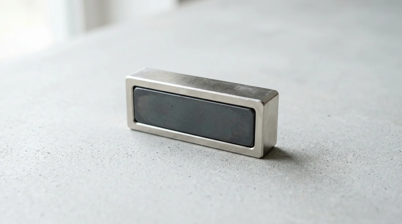
Manufacturing engineers are under constant pressure to make fixtures faster to change, safer to use, and easier to integrate into compact machinery. Rectangular pot magnets answer that need by combining a protected permanent magnet with a steel housing that concentrates holding force on one working face. Their linear shape makes them especially useful on conveyor frames, sheet-metal fixtures, robotic tooling, sensor brackets, and modular workholding systems where round magnets may not distribute load efficiently. This article explains why engineers specify this geometry, how the magnetic circuit improves performance, and what practical factors matter when selecting these assemblies for modern production environments.
Strategic Value of Rectangular Pot Magnets
In modern industrial environments, the demand for modular, non-destructive fixturing has driven a shift in how engineers approach holding and positioning tasks. At the core of this transition is the utilization of magnetic assemblies designed to maximize clamping force within constrained physical envelopes. Unlike traditional mechanical clamps that require drilling, tapping, or complex pneumatic routing, magnetic solutions offer rapid engagement and release. This flexibility is critical for facilities adopting agile manufacturing methodologies, where production lines must be reconfigured efficiently to accommodate different product iterations.
Among the various geometries available, the rectangular profile has emerged as a strategic choice for specific structural integrations. By aligning with the linear edges of conveyor systems, structural beams, and tooling jigs, these assemblies provide a continuous line of magnetic contact. This geometric advantage is particularly useful when dealing with flat sheet metal or linear steel tracks, where round assemblies might leave critical gaps or fail to distribute the clamping load evenly across the contact surface.
Why Engineers Specify Rectangular Pot Magnets
The fundamental reason engineers specify a Rectangular Pot Magnet over alternative holding mechanisms lies in the physics of its magnetic circuit. In a standard configuration, a permanent magnet is encased within a customized steel channel or cup. This steel housing acts as a flux concentrator, redirecting the magnetic lines of force that would normally radiate from the back and sides of the magnet. By channeling these flux lines to the single open face of the assembly, the effective holding power is multiplied.
Quantitative testing demonstrates that this channeled design can increase the perpendicular pull force compared to a bare, unhoused magnet of the exact same volume and grade. For engineers constrained by strict weight and space limitations—such as in robotic end-of-arm tooling or compact sensor housings—this high force-to-volume ratio is highly advantageous. Furthermore, unlike round magnets, the rectangular geometry introduces specific edge effects. The magnetic field is not perfectly uniform across the face; flux tends to concentrate along the linear edges and corners. This extended linear footprint allows for multi-point load distribution, spreading the concentrated force to prevent localized deformation on thin-gauge steel components.
How Rectangular Pot Magnets Differ from Exposed Magnets
Bare or exposed permanent magnets, particularly high-strength neodymium variants, present several operational challenges in a heavy manufacturing setting. First, sintered neodymium is inherently brittle; direct mechanical impact against a steel surface can easily cause the magnet to chip, shatter, or degrade over time. Second, an exposed magnet projects a deep, omnidirectional magnetic field. In a factory setting, this unshielded flux gathers ambient ferrous dust, metal shavings, and machining swarf, which eventually compromises the mating surface and reduces holding power.
Pot magnets resolve both of these vulnerabilities. The steel casing provides a robust mechanical shield, absorbing the kinetic energy of repeated clamping cycles and protecting the fragile magnetic core from direct impact. Furthermore, the housing effectively contains the stray magnetic field. Measurements indicate that stray magnetic flux is reduced beyond the immediate working face of the assembly. This containment is crucial when mounting magnets in close proximity to sensitive electronic sensors, programmable logic controllers (PLCs), or navigation systems in automated guided vehicles (AGVs), where magnetic interference could cause critical system faults.
Key Specifications for Engineering Selection

Selecting the appropriate magnetic assembly requires a rigorous evaluation of mechanical, environmental, and magnetic variables. Engineers cannot rely solely on the maximum advertised holding capacity; they must account for the specific conditions under which the magnet will operate. A comprehensive specification process evaluates the direction of the applied load, the operating environment's thermal profile, and the structural limitations of the mating surface.
Pull Force, Shear Resistance, and Air Gap
The most commonly cited metric for any magnetic assembly is its perpendicular pull force—an idealized value derived from testing against a thick, flat, clean, low-carbon steel plate. However, in practical manufacturing applications, forces are rarely perfectly perpendicular, and surfaces are rarely ideal. Engineers must explicitly derate these published values when working with thin-gauge, painted, curved, or contaminated surfaces. When a magnet is mounted on a vertical surface, such as a warehouse beam or a machine enclosure, it is subjected to shear force (sliding down the surface). Due to the low coefficient of friction between polished steel and plated magnets, shear resistance is typically a fraction of the rated perpendicular pull force. To combat this, engineers often incorporate rubberized coatings or friction pads, which can improve shear resistance.
Another critical variable is the air gap. Magnetic strength follows an inverse-square law, meaning that even microscopic separations between the magnet and the target surface cause a drastic reduction in holding power. An air gap of just 0.5mm—often caused by layers of industrial paint, powder coating, or accumulated dust—can significantly reduce the effective clamping force. Engineers must specify magnets with a deeper magnetic field reach if significant air gaps are anticipated in the application.
Magnet Materials, Coatings, and Housings
The internal core material dictates the assembly's baseline strength and thermal resilience. Neodymium-Iron-Boron (NdFeB) is the industry standard for high-strength applications, offering the highest magnetic energy product available. However, standard N35 to N52 grades suffer irreversible flux loss if operating temperatures exceed 80°C. For high-temperature environments, such as near injection molding presses or welding stations, engineers must specify high-coercivity neodymium (rated up to 150°C) or transition to Ceramic (Ferrite) cores, which can withstand continuous exposure up to 250°C despite having a lower baseline pull force. Furthermore, engineers must consider the thermal limits of the epoxy or potting material used to bond the magnet inside the steel cup. Often, these adhesives degrade at temperatures well below the magnet's actual Curie limit, dictating the real-world maximum operating temperature of the entire assembly.
Coatings and housings are equally vital for longevity. The standard protective layer for neodymium cores is a triple-layer Nickel-Copper-Nickel (Ni-Cu-Ni) plating. While sufficient for dry indoor use, humid or caustic environments dictate the use of epoxy coatings or 304/316 stainless steel housings. Stainless steel housings prevent galvanic corrosion but introduce a slight, unavoidable air gap due to the non-magnetic nature of the steel, requiring a stronger internal magnet to achieve the same surface holding force.
Specification Comparison Table
To streamline the selection process, the following table compares the primary engineering specifications of the two most common core materials used in these assemblies.
| Specification Metric | Standard Neodymium (NdFeB) Core | Ceramic (Ferrite) Core |
|---|---|---|
| Maximum Operating Temp | 80°C (up to 150°C for high-temp grades) | 250°C (up to 300°C for specialized grades) |
| Pull Force Density | High (varies by width, height, and grade) | Moderate (varies by width, height, and grade) |
| Shear Force Capacity | Fraction of Pull Force (friction dependent) | Fraction of Pull Force (friction dependent) |
| Corrosion Resistance | Low (Requires Ni-Cu-Ni or Epoxy coating) | High (Inherently resistant to oxidation) |
| Relative Cost (Per Unit) | High | Low |
Manufacturing Applications and Integration
The integration of magnetic assemblies into active production environments requires precise engineering to ensure repeatability and safety. Rather than serving as permanent structural fasteners, these components shine in dynamic applications where parts, tools, or sensors must be frequently positioned, held securely during a process, and subsequently released. Their application spans from heavy-duty material handling to the meticulous alignment of optical sensors on automated assembly lines.
Assembly Line Holding and Positioning
On high-speed assembly lines, maintaining precise alignment of components without introducing bottlenecks is a primary engineering challenge. Linear magnetic assemblies are frequently deployed as temporary clamps in welding jigs, woodworking fixtures, and CNC machining centers. By utilizing a Flanged Rectangular Magnet , engineers can bolt the assembly directly into a machined groove on the fixture base. The flanges provide mechanical stability against lateral torque, while the magnetic face securely holds the ferrous workpiece in place.
The payload capacity in these positioning applications is highly scalable. Depending on the surface area and the grade of the magnetic core, individual linear assemblies can offer clamping forces ranging from light-duty positioning to securing heavy steel plates during fabrication. By arraying multiple units along a conveyor guide rail, engineers can create a continuous holding force that stabilizes tall or top-heavy ferrous containers as they move through high-vibration zones.
Lean Manufacturing Support
Lean manufacturing principles, particularly the 5S system and SMED (Single-Minute Exchange of Die), rely heavily on reducing wasted motion and minimizing equipment changeover times. Magnetic holding systems are a useful component for these initiatives. In a SMED implementation, traditional bolted fixtures that require pneumatic tools and several minutes to swap can be replaced by magnetically anchored base plates.
Quantitative field data shows that replacing mechanical bolts with high-strength magnetic clamps can reduce fixture changeover times from minutes to seconds. Furthermore, in 5S shadow boards and tool organization systems, linear magnetic strips allow operators to return heavy tools to vertical storage boards quickly, improving workstation ergonomics and ensuring that critical instruments are always within a standardized reach radius.
Installation Steps That Reduce Errors
Proper installation is critical to prevent premature failure of both the magnet and the mating components. One of the most common integration methods involves utilizing a Rectangular Countersunk Magnet . The countersunk hole allows a standard flat-head machine screw to sit perfectly flush with or slightly below the magnetic surface, ensuring that the fastener does not interfere with the zero-gap contact required for maximum holding force.
Engineers must specify strict installation protocols to avoid damaging the brittle magnetic core. When securing countersunk assemblies , the recommended mounting torque for standard machine screws must be restricted to manufacturer-specified limits. Exceeding this torque threshold can cause the screw head to wedge against the internal magnet, leading to micro-fractures or catastrophic cracking of the neodymium. Additionally, machined mounting pockets should adhere to tight tolerances to prevent the steel housing from warping when bolted down.
Sourcing, Quality, and Cost Factors
Transitioning from a prototype design to full-scale manufacturing requires a rigorous approach to procurement. Sourcing magnetic components is not merely a matter of finding the lowest unit price; it involves auditing the supplier's quality control infrastructure, verifying material compliance, and understanding the hidden cost drivers that impact the total cost of ownership. Unreliable magnetic components can lead to catastrophic fixture failures, dropped payloads, and significant line downtime.
Supplier Documentation and Testing Methods
Reputable suppliers must provide comprehensive documentation to validate the performance of their magnetic assemblies. This typically includes a Certificate of Compliance (CoC) and detailed hysteresis graphs detailing the core's magnetic properties (Remanence, Coercivity, and Maximum Energy Product). For the finished assembly, engineers should demand statistically valid pull-test curves.
Standardized testing methodologies are crucial for comparative analysis. Pull force should be tested using a computerized tensile testing machine pulling perpendicular to a thick, flat, low-carbon steel test plate with a standardized surface roughness. Top-tier manufacturers maintain rigorous quality control systems, ensuring industry-standard low defect rates for dimensional and magnetic variances. Without this documented testing, engineers risk specifying components with unpredictable holding capacities.
Temperature, Corrosion, and Safety Factors
Environmental degradation is a leading cause of magnetic failure in industrial settings. To ensure longevity, the plating and housing must be validated against standardized environmental stressors. The most common benchmark is the Neutral Salt Spray (NSS) test, governed by standards such as ASTM B117 or ISO 9227.
A standard Ni-Cu-Ni plated assembly should successfully pass a standardized salt spray test without exhibiting red rust or significant blistering. For marine or highly corrosive chemical processing environments, engineers must specify encapsulated designs or specialized polymer coatings rated for extended NSS exposure. Safety factors must also be mathematically integrated into the design; standard engineering practice dictates a safety factor of 2:1 for static holding applications and 3:1 or 4:1 for overhead lifting or dynamic loads to account for unexpected shear forces, vibration, or partial surface contact. For overhead or dynamic lifting applications, magnetic fixtures must comply with recognized lifting equipment standards, such as ASME B30.20. Crucially, engineers must account for severe pinch hazards during installation and operation. Permanent magnets are generally unsuitable for dynamic overhead loads without dedicated secondary mechanical safety locks to prevent catastrophic drops in the event of shear shock or surface failure.
Cost Drivers Beyond Unit Price
While the raw cost of neodymium fluctuates based on global rare-earth commodity markets, several other factors heavily influence the final unit price of a magnetic assembly. Specifying tighter dimensional tolerances requires secondary precision grinding of the steel housing, which increases unit costs.
Material grade selection also drives cost. Upgrading from a standard core to a premium core increases the unit price, but this premium often allows engineers to utilize a smaller physical footprint to achieve the same clamping force, potentially saving money on the surrounding fixture materials. Finally, economies of scale play a massive role; Minimum Order Quantities (MOQs) for custom-machined housings are significantly higher than standard catalog sizes, impacting upfront capital expenditure for pilot production runs.
Decision Framework for Manufacturers
To prevent over-engineering or under-specifying, manufacturing teams must adopt a standardized decision framework for selecting holding mechanisms. This framework should objectively evaluate the total lifecycle requirements of the fixture, weighing the immediate benefits of magnetic clamping against long-term maintenance, safety, and operational constraints. By establishing clear selection criteria, engineers can ensure that magnetic assemblies are deployed only where they offer a distinct competitive advantage over mechanical or pneumatic alternatives.
Comparing Magnetic Holding Options
When comparing permanent magnetic assemblies to other fixturing technologies, energy consumption and infrastructure requirements are primary differentiators. Pneumatic clamps require a continuous supply of compressed air, airlines, and valves, introducing points of failure and ongoing energy costs. Electromagnets offer the advantage of switchable on/off control but require continuous electrical power to maintain their grip.
Permanent pot magnets , by contrast, require exactly 0 watts of holding power and zero external infrastructure. An equivalent electromagnet designed to hold 50 kg might continuously draw anywhere from 10 to 50 watts depending on the coil design, generating unwanted thermal output that can interfere with sensitive nearby instrumentation. The trade-off is that permanent magnets require mechanical force (such as a cam lever or sliding mechanism) to overcome the magnetic bond during the release phase, which must be factored into the ergonomic design of the workstation.
Maintenance and Safety Requirements
Despite being labeled 'permanent,' magnetic assemblies require standardized maintenance protocols to ensure safety. The steel faces must be periodically inspected for accumulated ferrous debris, which creates an artificial air gap and severely degrades holding force. Maintenance schedules should include wiping the magnetic faces with a non-abrasive cloth and inspecting the steel housings for signs of impact deformation or compromised plating. Personnel must also be trained on the severe pinch hazards associated with handling high-strength magnetic assemblies, particularly when positioning them near other ferrous components.
Demagnetization is a common concern among facility managers, but it is largely mitigated by proper specification. A correctly specified permanent magnet operating within its thermal limits loses a negligible amount of its magnetic flux density over its operational lifespan. Catastrophic flux loss only occurs if the magnet is exposed to temperatures exceeding its Curie point, subjected to massive opposing magnetic fields, or physically shattered through improper handling.
Final Selection Criteria
The final selection process can be distilled into a matrix that balances load requirements, environmental conditions, and cycle times. Engineers should use a structured approach to filter out incompatible options early in the design phase.
| Application Requirement | Recommended Fixturing Technology | Key Engineering Rationale |
|---|---|---|
| High-Speed Automated Release (100+ cycles/min) | Pneumatic or Electromagnet | Permanent magnets require mechanical force to detach, slowing high-speed automation. |
| Static Holding & Positioning (Zero Power) | Permanent Pot Magnet | 0 Watts required; failsafe holding even during facility power outages. |
| High Temperature Environment (>150°C) | Mechanical Clamp or Ferrite Magnet | Standard NdFeB magnets suffer irreversible flux loss above 80°C-150°C. |
| Low-Profile Linear Footprint | Rectangular Pot Magnet | Distributes heavy clamping force evenly across thin-gauge sheet metal without warping. |
By systematically applying these criteria, manufacturing engineers can confidently integrate magnetic technologies into their production lines. This analytical approach ensures that every chosen component directly contributes to improved cycle times, enhanced workspace organization, and robust, reliable holding power.
Further reading:
Key Takeaways
- Use rectangular pot magnets when a holding point must align with straight steel edges, conveyor rails, tooling jigs, or structural beams.
- Specify a potted design when the application needs higher holding force from a compact magnet by concentrating flux through one open face.
- Choose rectangular assemblies for thin-gauge or flat sheet-metal work where distributing clamping force along a longer footprint helps reduce localized deformation.
- Avoid exposed neodymium magnets in heavy manufacturing environments where impact, swarf, and ferrous dust can damage the magnet or reduce holding performance.
- Validate rated pull force under real operating conditions, including steel thickness, surface finish, air gaps, shear loads, and required safety factor.
Frequently Asked Questions
What is a rectangular pot magnet used for in manufacturing?
It is used for non-destructive holding, positioning, fixturing, sensor mounting, and temporary attachment on flat ferrous surfaces such as steel frames, jigs, conveyors, and tooling plates.
Why choose a rectangular pot magnet instead of a round one?
A rectangular profile matches linear edges, rails, beams, and sheet-metal surfaces more naturally, helping distribute holding force along a longer contact area and reducing gaps that round magnets may leave.
How does the steel pot improve magnetic holding force?
The steel housing redirects magnetic flux toward the open contact face, concentrating the field where holding is needed and improving the force-to-volume ratio compared with an exposed magnet.
Are rectangular pot magnets better than exposed neodymium magnets?
For factory use, often yes. The pot protects brittle neodymium from impact, reduces stray magnetic fields, and limits buildup of ferrous dust, swarf, and chips on non-contact surfaces.
Can rectangular pot magnets replace mechanical clamps?
They can replace clamps in many temporary or modular setups, especially when drilling, tapping, or pneumatic routing would slow line changes. Engineers should still verify load, surface condition, and safety factors.