 EN
EN AR
AR HR
HR CS
CS DA
DA NL
NL FI
FI FR
FR DE
DE EL
EL IT
IT JA
JA KO
KO NO
NO PL
PL PT
PT RU
RU ES
ES SV
SV IW
IW VI
VI TH
TH TR
TR FA
FA MS
MS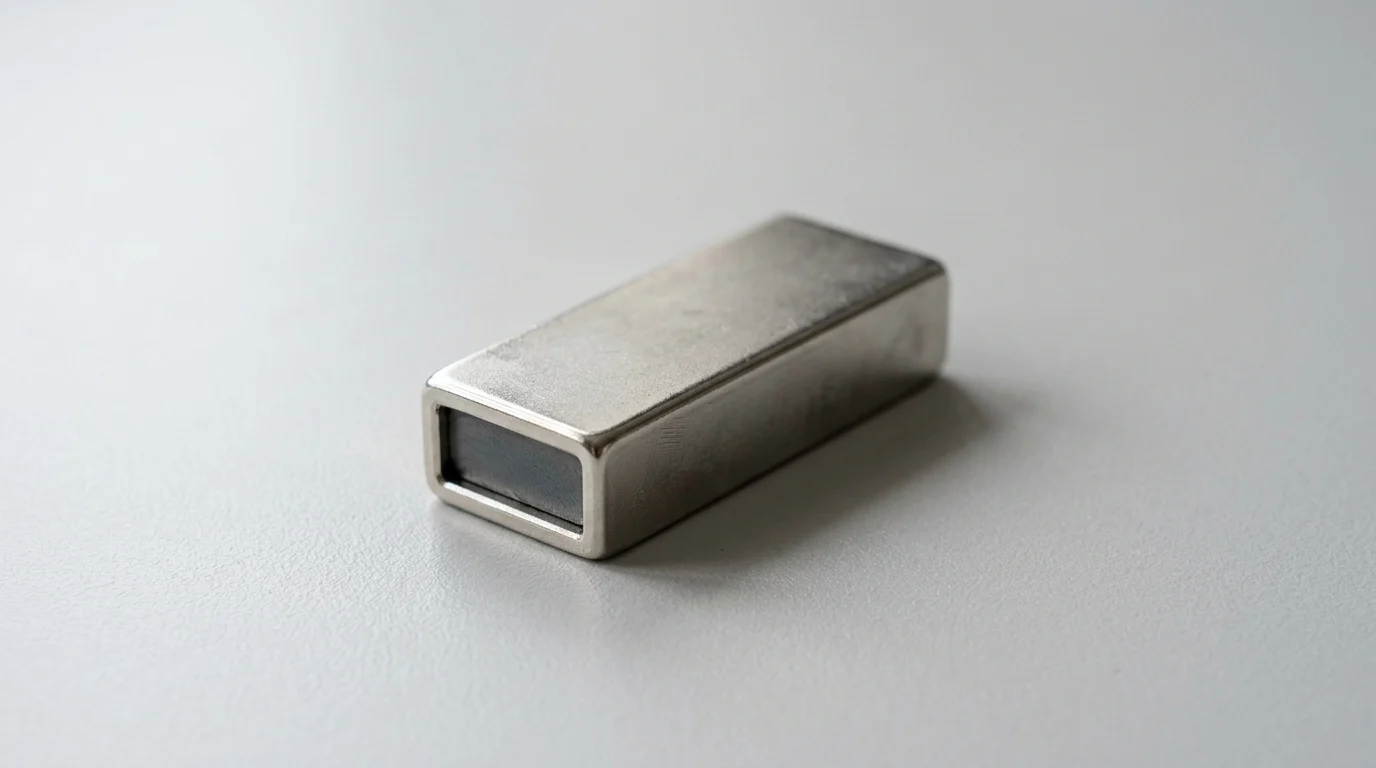
In automated production, small tooling choices can determine whether a line runs smoothly or loses precision at speed. Rectangular pot magnets offer a compact way to hold, locate, and transfer ferrous parts without external power, while their steel housings concentrate magnetic flux where the assembly needs it most. Compared with exposed magnets, the housed design improves durability, controls stray fields, and can increase localized pull force significantly. This article examines how their linear geometry supports robotic end-of-arm tooling, conveyor transfers, welding fixtures, and sheet metal handling, with attention to repeatability, mounting efficiency, and system-level performance.
Why Rectangular Pot Magnets Matter
Rectangular vs. Round Pot Magnets

While round pot magnets remain the industry standard for general-purpose holding due to their ease of manufacturing and installation via standard drill bits, they are not always the optimal choice for complex automated tasks. The decision to specify rectangular over round geometries hinges on load distribution, rotational stability, and the physical constraints of the automation equipment.
Key Technical Differences
The primary technical difference between rectangular and round pot magnets lies in their pole configuration and surface area utilization. Round pot magnets typically feature a concentric pole design, where the center acts as one pole and the outer steel rim acts as the opposite pole. Rectangular pot magnets utilize a linear multi-pole or bi-pole configuration, extending the magnetic field continuously along the length of the steel channel.
From a spatial efficiency standpoint, a rectangular magnet maximizes the active holding area within a linear bounding box. For example, when mounting a magnet into a 15 mm wide channel, a rectangular magnet utilizing the full length of the channel can offer up to 25% to 35% more magnetic contact area than a series of 15 mm diameter round magnets spaced along that same channel. This increased contact area translates directly to higher holding forces without requiring a wider footprint.
When Rectangular Designs Improve Stability
Rectangular designs dramatically improve mechanical stability when handling elongated, cylindrical, or asymmetrical payloads. A single round magnet provides a single point of contact; if the payload's center of gravity is offset, the part can easily pivot or rotate around the magnet's axis. To prevent this, engineers must typically install two or more round magnets, increasing alignment complexity and component count.
A single rectangular pot magnet inherently resists rotational forces due to its extended contact line. For instance, in automated pipe handling, a rectangular magnet with a V-notch or flat face can provide greater than 15 Nm of torsional resistance against the pipe, completely preventing rotation during high-speed robotic transfers. This anti-rotational characteristic is invaluable when feeding parts into CNC machining centers or automated stamping presses where precise angular orientation is mandatory.
Trade-Offs Against Vacuum and Mechanical Clamping
When designing end-of-arm tooling or workholding fixtures, engineers frequently evaluate rectangular pot magnets against vacuum cups and pneumatic mechanical clamps. Each technology presents distinct operational trade-offs regarding speed, energy consumption, and environmental tolerance.
| Clamping Technology | Energy Requirement | Actuation Speed | Typical Maintenance | Ideal Environment |
|---|---|---|---|---|
| Rectangular Pot Magnet | Zero (Permanent) | Instantaneous | Minimal (Visual check) | High heat, dust, oil |
| Vacuum Cups | Continuous Compressed Air | 50 - 200 ms | High (Cup wear, filter clogs) | Clean, flat, non-porous |
| Pneumatic Clamps | Compressed Air (0.6 MPa) | 100 - 300 ms | Moderate (Seal wear, lubrication) | High shear loads, irregular shapes |
As illustrated, rectangular pot magnets excel in environments where compressed air is unavailable, costly, or prone to failure. They are immune to the pressure drops that plague pneumatic systems and are unaffected by oily or dusty surfaces that cause vacuum cups to lose suction. However, permanent magnets lack the ability to actively release a part without mechanical stripping mechanisms, a trade-off that must be managed through proper fixture design.
Key Selection Specifications
Specifying the correct rectangular pot magnet requires a rigorous analysis of the magnetic circuit's capabilities and the physical environment of the assembly line. Relying solely on the manufacturer's maximum pull force rating frequently leads to system failures, as real-world automated applications introduce dynamic loads, varying surface finishes, and environmental stressors.
Holding Force, Shear Resistance, and Air Gaps
The nominal holding force of a rectangular pot magnet is tested under ideal conditions: a direct perpendicular pull from a thick, perfectly flat, clean, low-carbon steel plate. In automated assembly, these ideal conditions are rare. Engineers must account for shear force—the sliding force parallel to the magnet's face. Without high-friction rubber or polyurethane coatings, the shear resistance of a bare steel pot magnet is typically only 15% to 20% of its rated perpendicular pull force.
Furthermore, air gaps drastically degrade magnetic performance. An air gap can be created by paint, plating, rust, or uneven surfaces on the target payload. Because the magnetic circuit of a pot magnet is highly concentrated and shallow, even a microscopic separation causes a severe drop in magnetic flux. Introducing an air gap of just 0.5 mm can reduce the effective holding force of a rectangular pot magnet by up to 50%. Engineers must map the theoretical pull curve against the expected air gap tolerances of the incoming production parts.
Magnet Materials, Coatings, and Housings
The selection of the internal magnetic alloy dictates the operational temperature limits and baseline strength of the assembly. Neodymium (NdFeB) offers the highest magnetic energy density, making it ideal for compact, high-strength automated grippers. Standard NdFeB grades operate safely up to 80°C, while specialized high-temperature grades (such as EH or AH) can withstand up to 200°C. For extreme environments, such as automated hot-stamping or welding lines exceeding 250°C, Samarium Cobalt (SmCo) is required, despite its higher cost and lower maximum energy product.
Coatings and housing materials are equally critical for longevity. The internal magnets are highly susceptible to oxidation and must be protected. A standard Ni-Cu-Ni electroplated coating (typically 10 to 20 µm thick) provides excellent corrosion resistance for general factory environments. The outer channel is most commonly manufactured from Q235 carbon steel to optimize flux transfer; however, in food-grade or medical automation, 304 or 316 stainless steel housings are utilized, though they slightly reduce the overall magnetic efficiency due to their lower magnetic permeability.
Mounting Options, Tolerances, and Pole Layout
Integrating rectangular pot magnets into automated machinery requires precise dimensional tolerances and secure mounting protocols. Standard rectangular channels are typically manufactured with dimensional tolerances of $pm$0.1 mm on length and width, ensuring they fit predictably into milled slots on fixture plates.
Mounting options generally include countersunk through-holes, threaded blind holes on the rear, or extended mounting flanges. The internal pole layout—whether a single continuous North pole flanked by South pole channel walls, or alternating N-S poles along the length—affects the depth of the magnetic field. Multi-pole layouts create a very strong but shallow field, ideal for gripping thin sheet metal (0.5 mm to 2.0 mm thick) without magnetizing adjacent layers in a stack.
| Magnet Material | Max Operating Temp (°C) | Remanence ($B_r$) (Tesla) | Intrinsic Coercivity ($H_{cj}$) (kA/m) | Relative Cost Index |
|---|---|---|---|---|
| NdFeB (Standard) | 80 | 1.35 - 1.45 | > 955 | Moderate |
| NdFeB (High-Temp) | 200 | 1.15 - 1.25 | > 2388 | High |
| SmCo (Standard) | 350 | 1.00 - 1.10 | > 1432 | Very High |
| Ferrite (Ceramic) | 250 | 0.38 - 0.40 | > 215 | Low |
Integration, Testing, and Maintenance
A successful deployment of rectangular pot magnets relies heavily on strict adherence to installation protocols and rigorous lifecycle testing. Even the most highly specified magnet will fail if misaligned, over-torqued, or subjected to uncalculated dynamic forces during robotic articulation.
Installation and Alignment Steps
Installation must ensure that the working face of the rectangular pot magnet is perfectly flush with, or precisely protruding from, the surrounding fixture. If the magnet is recessed into an aluminum tooling plate by even 0.2 mm, the resulting air gap will severely compromise the payload grip. Conversely, if it protrudes unevenly, it can cause the payload to tilt, leading to alignment errors in downstream assembly steps.
When securing the magnets using countersunk fasteners, torque control is paramount. The magnetic material inside the channel is essentially a sintered ceramic and is highly brittle. Over-tightening a mounting screw can cause the internal magnet to crack, altering the magnetic flux and creating loose debris. For standard M5 countersunk screws used in these assemblies, engineers should enforce a maximum torque specification of 5 to 7 Nm, utilizing thread-locking compounds to prevent loosening under vibration.
Validation Under Real Operating Conditions
Static holding force calculations must be validated against the dynamic realities of the automated system. High-speed delta robots or heavy-duty 6-axis articulated arms subject payloads to significant acceleration and deceleration vectors. A robotic arm executing a rapid transfer might subject the payload to acceleration profiles ranging from 2G to 4G.
To validate the system, engineers perform dynamic drop tests and shear tests under maximum programmed velocities. Industry standards for magnetic lifting and automated overhead transfers dictate a minimum safety factor of 3:1. This means that if a steel component weighs 10 kg, the rectangular pot magnet configuration must possess a tested, real-world holding force (accounting for actual surface finish and air gaps) of at least 30 kg. For applications involving rapid emergency stops (E-stops) where deceleration spikes are highest, a 5:1 safety factor is highly recommended.
Failure Modes and Maintenance Checks
While permanent magnets are inherently low-maintenance, they are not immune to degradation. The most common failure mode in automated environments is mechanical chipping caused by repeated high-velocity impacts against steel payloads. Over millions of cycles, the epoxy or resin potting that secures the magnet inside the steel channel can degrade, leading to internal shifting.
Thermal demagnetization is another risk if the ambient or conductive temperature exceeds the magnet's coercive threshold. Once a permanent magnet loses flux due to heat, the loss is irreversible without factory remagnetization. Maintenance protocols should mandate visual inspections of the magnet face for cracking or excessive debris accumulation (such as iron shavings) every 50,000 cycles or every 6 months. Additionally, a periodic pull-test using a calibrated load cell ensures the magnetic circuit has not degraded over time.
Sourcing and Final Decision Criteria
Transitioning from prototype to full-scale automated production requires a strategic approach to sourcing. The procurement of rectangular pot magnets must balance strict quality assurance standards with supply chain logistics, ensuring that the components delivered meet exact dimensional and magnetic tolerances batch after batch.
Supplier Quality, Traceability, and Compliance
Supplier quality management is the foundation of reliable automation. Procurement teams must source from manufacturers operating under stringent quality frameworks, such as ISO 9001 or, for automotive applications, IATF 16949. These certifications ensure that the supplier maintains strict control over the raw material smelting, sintering, and machining processes, which directly impact the uniformity of the magnetic flux.
Compliance with environmental directives like RoHS and REACH is also mandatory, particularly concerning the heavy metals used in electroplating processes. To guarantee traceability throughout the lifecycle of the automation equipment, buyers should require laser etching on the steel housing of the rectangular pot magnets, detailing the batch number, date of manufacture, and specific magnetic grade. This traceability allows engineers to isolate and replace specific batches if an anomaly is detected during production.
Cost Drivers, Lead Times, and Customization
Cost drivers for rectangular pot magnets extend beyond the raw market price of Neodymium or Samarium Cobalt. While standard sizes are mass-produced and cost-effective, automated systems frequently require custom lengths, specific hole placements, or non-standard thread sizes. Customizing the steel channel involves upfront CNC machining or extrusion tooling costs.
When specifying custom geometries, Minimum Order Quantities (MOQs) become a critical factor. Manufacturers typically require MOQs ranging from 1,000 to 5,000 units to offset the setup costs for custom profiles, whereas standard off-the-shelf units can be purchased in single-digit quantities. Lead times must also be factored into the project schedule; standard components typically require 4 to 6 weeks for delivery, while custom-engineered rectangular pot magnets may extend lead times to 8 to 10 weeks, depending on the complexity of the housing and the availability of specific high-temperature magnetic grades.
Decision Matrix for Selecting Rectangular Pot Magnets
Final selection relies on a weighted decision matrix that evaluates the technical, environmental, and commercial constraints of the project. Engineers must first lock in the payload weight and the dynamic acceleration (G-forces) to determine the absolute minimum holding force and required safety factor (e.g., 3:1).
Next, the operating environment dictates the materials: temperatures exceeding 80°C necessitate high-grade NdFeB or SmCo, while corrosive environments mandate specialized coatings or stainless-steel housings. Finally, the integration footprint is evaluated to determine if a standard rectangular profile can be utilized or if a custom-machined channel is required to fit the end-of-arm tooling. By systematically applying these criteria, automation engineers can secure a workholding solution that maximizes uptime, guarantees precision, and optimizes the overall lifecycle cost of the assembly line.
Key Takeaways
- Use rectangular pot magnets when an automated system needs compact linear holding with a limited mounting footprint.
- Choose a housed pot magnet design to concentrate flux at the working face and achieve up to 30% to 40% higher localized pull force than a comparable raw magnet.
- Match rectangular magnets to 20x20 mm or 40x40 mm automation profiles to reduce adapter plates, tooling weight, and robot moment of inertia.
- Integrate rectangular pot magnets into machined slots or channels when sub-millimeter positioning and repeatability near ±0.05 mm are required.
- Use longer rectangular pot magnets for welding fixtures and thin sheet handling to distribute clamping force and reduce bowing or distortion.
Frequently Asked Questions
What makes rectangular pot magnets different from raw magnets?
They place a permanent magnet inside a steel channel or housing, which protects the brittle magnet and concentrates magnetic flux at the working face for stronger, more controlled holding.
Why are rectangular pot magnets useful in robotic end-of-arm tooling?
Their linear shape matches common automation profiles such as 20x20 mm and 40x40 mm aluminum extrusions, helping reduce adapter plates, tooling weight, and robot inertia.
Can rectangular pot magnets deliver higher holding force?
Yes. A well-designed pot magnet can provide about 30% to 40% higher localized pull force than an unhoused magnet of similar volume by directing flux through the steel housing.
Do rectangular pot magnets help reduce magnetic interference?
Yes. The steel casing helps confine stray magnetic fields along the sides and back, lowering the risk of interference with nearby sensors, AGVs, or adjacent metal components.
Where are rectangular pot magnets commonly used in automation?
They are used in robotic pick-and-place tools, conveyor transfer stations, automated welding fixtures, sheet metal handling, and linear clamping systems where compact, repeatable holding is required.