 EN
EN AR
AR HR
HR CS
CS DA
DA NL
NL FI
FI FR
FR DE
DE EL
EL IT
IT JA
JA KO
KO NO
NO PL
PL PT
PT RU
RU ES
ES SV
SV IW
IW VI
VI TH
TH TR
TR FA
FA MS
MS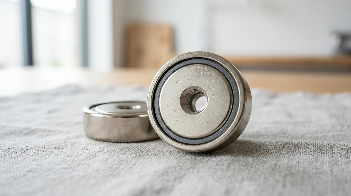
In factories, workshops, and equipment installations, the best fastening method is not always a bolt, clamp, or weld. Medium size pot magnets offer a compact way to hold, position, lift, or mount ferrous parts without permanent surface damage. Typically ranging from 25 mm to 60 mm in diameter, these magnetic assemblies can deliver substantial holding force by concentrating magnetic flux through a steel cup. That makes them valuable for jigs, fixtures, guards, signage, sensor mounts, and quick-change tooling. This article explains how they work, where they are used, and what engineers should consider when choosing between NdFeB, ferrite, threaded, countersunk, rubber-coated, or custom pot magnet designs.
What Are Medium Size Pot Magnets
Medium size pot magnets represent a critical intersection of mechanical fastening and magnetic workholding, providing engineers with highly efficient, low-profile gripping solutions. Unlike raw permanent magnets, which emit magnetic flux symmetrically in all directions, pot magnets utilize a specialized ferromagnetic housing to manipulate the magnetic circuit. This design maximizes the holding force on a single active face while protecting the brittle magnetic material from mechanical impacts.
In industrial environments where space is constrained but significant holding power is required, medium size pot magnets offer a versatile alternative to traditional mechanical clamps, bolts, and pneumatic actuators. Their integration simplifies assembly processes, reduces the need for surface penetration, and allows for rapid deployment and reconfiguration of temporary or semi-permanent fixtures.
Definition and Common Sizes
In industrial nomenclature, the "medium size" classification typically denotes pot magnets with an external diameter ranging from 25 mm to 60 mm. Within this dimensional envelope, the assemblies are large enough to generate substantial holding forces but remain compact enough for integration into dense machinery enclosures or robotic end-of-arm tooling.
Depending on the internal magnetic material and the specific design of the steel cup, a medium size pot magnet within this 25 mm to 60 mm range generally delivers a theoretical holding force spanning from 150 N (approximately 15 kg) up to 1,000 N (100 kg) under ideal, zero-air-gap conditions. The overall height or thickness of these units usually ranges from 5 mm to 15 mm, making them highly suitable for low-profile applications where vertical clearance is limited.
Why Engineers Use Them
Engineers specify pot magnets primarily to harness their amplified magnetic efficiency. By encasing a raw permanent magnet—such as Neodymium (NdFeB) or Ferrite—inside a low-carbon steel cup, the magnetic flux lines that would normally radiate from the back and sides of the magnet are redirected to the front working face. This flux concentration can increase the effective holding force by up to three times compared to an unhoused magnet of identical volume.
Beyond magnetic performance, the steel housing provides essential mechanical protection. Permanent magnet alloys, particularly sintered Neodymium and Samarium Cobalt, are inherently brittle and prone to chipping or shattering upon high-velocity impact with steel surfaces. The pot enclosure absorbs these mechanical shocks, extending the operational lifespan of the component in rigorous factory environments. Furthermore, the steel cup allows for conventional machining—such as threading or counterboring—which is virtually impossible to perform directly on a sintered magnet.
Typical Designs and Mounting Options
To accommodate diverse engineering requirements, manufacturers produce medium size pot magnets with several standard mounting geometries. The internal magnet is typically secured within the housing using high-strength industrial epoxy, leaving the steel shell available for various mechanical interfaces.
| Mounting Design | Typical Interface | Ideal Application | Torque Limitation (Typical M6) |
|---|---|---|---|
| Countersunk | Flathead machine screw | Flush surface mounting, jigs | 3.0 - 5.0 Nm |
| Counterbored | Socket head cap screw | Heavy-duty fixtures, tooling | 4.0 - 6.0 Nm |
| Internal Thread | Threaded rod or bolt | Suspended installations, sensors | 5.0 - 8.0 Nm |
| External Stud | Nuts and washers | Direct insertion into brackets | 5.0 - 8.0 Nm |
Countersunk and counterbored designs are highly favored for applications requiring a flush mating face, ensuring the fastener head does not interfere with the active magnetic area. Conversely, internal threaded bosses and external threaded studs provide robust, standalone attachment points that are easily integrated into modular aluminum extrusion profiles or robotic gripper plates.
Industrial Applications
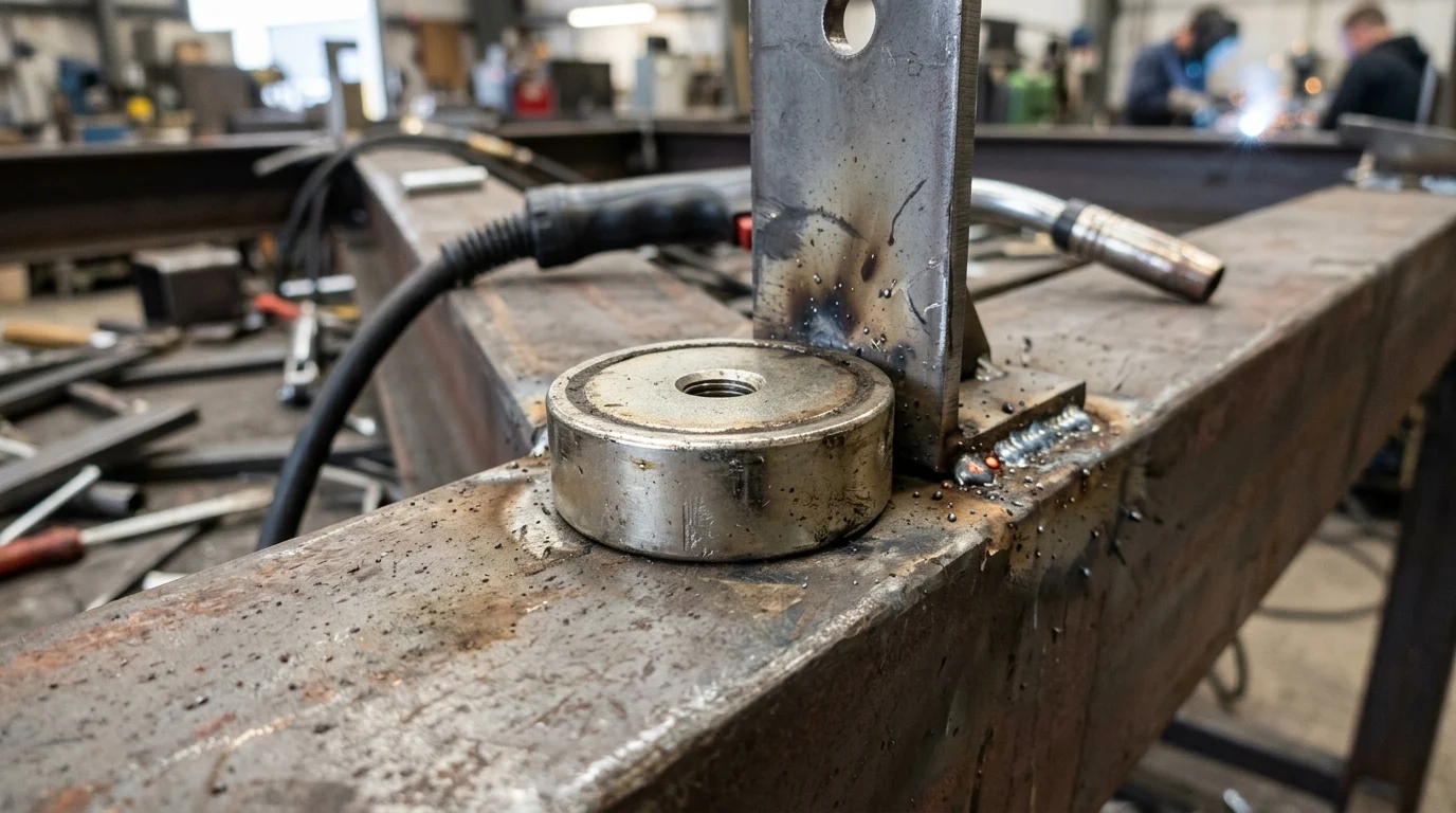
The mechanical and magnetic properties of medium size pot magnets translate into broad utility across the factory floor and assembly line. By eliminating the need for complex mechanical clamping systems, these magnetic assemblies streamline production workflows and enhance operational flexibility.
From temporary holding during fabrication to the reliable securing of safety enclosures, the predictable holding force of the 25 mm to 60 mm diameter range makes these magnets an industry standard for rapid, tool-less engagement.
Jigs and Fixtures
In welding, machining, and assembly operations, jigs and fixtures require rapid deployment and rigid holding. Medium pot magnets, particularly those generating 300 N to 800 N of pull force, are frequently utilized to anchor workpieces or secure modular fixture plates to optical tables and welding benches.
Because the magnetic flux is contained entirely at the working face, pot magnets do not magnetize the surrounding fixture or interfere with sensitive nearby instrumentation. This containment is crucial in welding applications, where stray magnetic fields can cause arc blow, leading to defective welds. By embedding countersunk pot magnets into custom fixture blocks, operators can achieve repeatable positioning with a tolerance of less than 0.1 mm, drastically reducing setup times between production batches.
Machine Guards and Access Panels
Industrial machinery must comply with stringent safety standards regarding moving parts and high-voltage enclosures. Removable machine guards and access panels frequently utilize medium size pot magnets to ensure secure closure without the need for specialized tools, facilitating quick access for maintenance personnel.
In these applications, engineers must carefully calibrate the holding force. A typical access panel might require a combined breakaway force of 100 N to 200 N to prevent accidental dislodgement or rattling under machinery vibration (commonly in the 10 Hz to 50 Hz range). However, the force must not exceed ergonomic limits, ensuring a technician can manually overcome the magnetic pull. Pot magnets with rubberized coatings or polyurethane caps are often deployed here to dampen vibration and prevent scratching of painted enclosures.
Material Handling and Positioning
Automated material handling and robotics rely heavily on predictable, repeatable gripping forces. Medium size pot magnets are frequently integrated into End-of-Arm Tooling (EOAT) for pick-and-place operations involving ferrous components such as stamped automotive body panels, steel pipes, or appliance housings.
A 50 mm diameter Neodymium pot magnet weighing less than 100 grams can reliably lift a 20 kg steel component, offering an exceptional strength-to-weight ratio that maximizes the payload capacity of the robotic arm. In conveying systems, fixed pot magnets are used as non-contact guides or holding stations to stabilize ferrous items as they move along high-speed production lines, ensuring alignment without introducing mechanical friction.
Performance Factors to Compare
Evaluating the performance of medium size pot magnets requires analyzing both the magnetic circuit and the operational environment. The theoretical specifications provided by manufacturers are established under ideal laboratory conditions, which rarely reflect the realities of industrial deployment.
Engineers must account for multiple variables—including directional loads, environmental exposure, and the physical characteristics of the mating surface—to ensure the selected magnet performs reliably throughout its intended lifecycle.
Holding Force, Shear Load, and Air Gap
The most critical distinction in magnetic workholding is the difference between direct pull force (normal force) and shear load (sliding force). The advertised holding force of a pot magnet assumes a direct, perpendicular pull away from a thick, flat, and clean steel plate. However, when the magnet is mounted vertically and subjected to a downward sliding force, the holding capacity drops significantly.
Due to the low coefficient of friction between polished steel surfaces, the shear load capacity of a standard pot magnet is typically only 15% to 30% of its direct pull force. Furthermore, the introduction of an air gap—caused by paint, rust, or uneven surfaces—drastically degrades the magnetic flux penetration.
| Air Gap Thickness (mm) | Direct Pull Force Retention (%) | Shear Load Capacity Retention (%) |
|---|---|---|
| 0.0 (Direct Contact) | 100% | ~20 - 30% |
| 0.5 mm | ~45 - 55% | ~10 - 15% |
| 1.0 mm | ~25 - 35% | ~5 - 10% |
| 2.0 mm | ~10 - 15% | < 5% |
To combat low shear resistance, engineers often specify pot magnets with integrated rubber jackets or incorporate mechanical lips into the fixture design to bear the shear weight, relying on the magnet solely for normal clamping force.
Magnet Material, Coating, and Temperature Limits
The core material of the pot magnet dictates both its maximum holding strength and its thermal limitations. Neodymium (NdFeB) is the standard for high-strength applications, offering the highest energy product (BHmax). However, standard commercial NdFeB grades (e.g., N35 to N52) suffer from irreversible flux loss at temperatures exceeding 80°C. High-temperature grades (denoted by suffixes like M, H, SH, or UH) can push this limit to 150°C or 180°C, but at a premium cost.
For applications involving extreme heat, such as plastic injection molding or industrial baking, Ferrite (ceramic) or Samarium Cobalt (SmCo) pot magnets are preferred. While Ferrite produces roughly one-third the holding force of Neodymium for a given size, it can operate continuously at 250°C without permanent degradation. SmCo offers a compromise, providing near-Neodymium strength with temperature stability up to 300°C or 350°C.
Surface Condition, Corrosion, and Vibration
The condition of the mating surface is a primary driver of magnetic efficiency. A high surface roughness (e.g., Ra 12.5 or greater) creates microscopic air gaps that prevent the magnetic flux lines from fully penetrating the workpiece. For optimal performance, the mating steel should have a surface finish of Ra 3.2 or finer.
Corrosion and vibration present ongoing risks to the assembly. Standard Neodymium magnets are highly susceptible to oxidation and are typically protected by a triple-layer Ni-Cu-Ni plating (10 to 20 microns thick). The steel cup is usually zinc-plated. In highly corrosive environments, such as marine or chemical processing facilities, completely encapsulated, rubber-coated pot magnets or stainless-steel housings (typically utilizing 304 or 316 series steel, though this slightly reduces flux concentration) are mandatory to prevent catastrophic failure of the magnetic alloy.
Selection, Installation, and Procurement
Successfully integrating medium size pot magnets into an industrial application requires a structured approach to selection, installation, and supply chain management. Specifying the correct magnet involves more than simply matching a catalog pull force to a payload weight.
Procurement and engineering teams must collaborate to establish appropriate safety margins, define installation protocols, and audit suppliers to ensure consistent metallurgical quality and dimensional accuracy across high-volume production runs.
Load Case, Safety Factor, and Mounting Geometry
Engineers must apply rigorous safety factors based on the specific load case and the potential consequences of failure. For static, horizontal holding applications where failure does not present a safety risk, a safety factor of 2:1 or 3:1 relative to the theoretical holding force is standard practice.
However, if the pot magnets are used in dynamic applications, overhead positioning, or scenarios involving high vibration, the safety factor should be increased to 5:1 or even 10:1. The mounting geometry must also be evaluated; for instance, leveraging a counterbored magnet with an M6 socket head cap screw provides a higher tensile yield strength than a countersunk screw, making it preferable for applications subjected to sudden shock loads or heavy cyclic fatigue.
Installation, Inspection, and Maintenance
Improper installation frequently leads to premature failure of the magnet assembly. The most common error is over-torquing the central fastener. Because the permanent magnet material is brittle, excessive compressive force from a screw head can crack the magnet or compromise the epoxy bond holding the magnet within the steel cup. For a medium size pot magnet utilizing an M6 fastener, the maximum installation torque should generally not exceed 5.0 to 8.0 Nm, depending on the specific design.
Routine maintenance and inspection protocols should focus on visual and functional checks. Technicians should inspect the active face for accumulated ferrous debris (swarf), which acts as an artificial air gap and severely reduces holding force. Additionally, inspectors should look for chipped plating or cracked epoxy, as these defects expose the underlying Neodymium to atmospheric moisture, inevitably leading to rapid oxidation and volumetric expansion of the magnet.
Cost, Supplier Quality, and Buying Criteria
Procurement professionals must balance unit cost with metallurgical quality and machining precision. In the medium size category (25 mm to 60 mm), standard Commercial-Off-The-Shelf (COTS) Neodymium pot magnets typically range from $2.50 to $15.00 per unit, depending on the exact dimensions, magnet grade, and complexity of the steel housing.
When sourcing these components, especially at industrial volumes, buyers should evaluate suppliers based on their defect rates and testing methodologies. A reputable supplier should maintain a defect rate below 0.1% and provide demagnetization curves and pull-force test reports for each production batch. Minimum Order Quantities (MOQs) for custom designs or specialized high-temperature grades usually start between 500 and 1,000 units, whereas standard zinc-plated N35 pot magnets are readily available in smaller batches through major industrial distributors.
Key Takeaways
- Specify medium size pot magnets when a 25 mm to 60 mm diameter holding solution is needed for compact fixtures, machinery, or removable mounts.
- Use the rated holding force only as a best-case reference because paint, curvature, roughness, thin steel, and air gaps can sharply reduce real-world performance.
- Choose NdFeB pot magnets for maximum holding force in limited space and ferrite pot magnets for cost-effective general-duty applications.
- Select the mounting style—countersunk, straight hole, threaded, stud, hook, or rubber-coated—based on load direction, installation method, and surface protection needs.
- Protect long-term holding reliability by matching the pot magnet to the working temperature, corrosion exposure, vibration level, and required safety factor.
Frequently Asked Questions
What sizes are considered medium size pot magnets?
Medium size pot magnets are typically 25 mm to 60 mm in diameter, with low-profile heights often around 5 mm to 15 mm. This range balances compact installation with meaningful industrial holding force.
How much holding force can a medium pot magnet provide?
Depending on magnet material, cup design, surface condition, and air gap, medium pot magnets commonly provide about 150 N to 1,000 N under ideal contact conditions.
Why are pot magnets stronger than bare magnets of similar size?
A steel pot redirects magnetic flux toward one working face, concentrating the magnetic circuit. This can significantly increase usable holding force while also protecting brittle NdFeB or ferrite magnets from impact damage.
Where are medium size pot magnets commonly used in industry?
They are used in fixtures, jigs, signage, machine guards, sensor mounts, robotic tooling, temporary workholding, and equipment installation where compact, removable holding is preferred over drilling or welding.
What mounting styles are available for medium pot magnets?
Common options include countersunk holes, straight holes, threaded studs, internal threads, rubber-coated housings, hooks, and brass or steel pot designs for different fixture and installation requirements.