 EN
EN AR
AR HR
HR CS
CS DA
DA NL
NL FI
FI FR
FR DE
DE EL
EL IT
IT JA
JA KO
KO NO
NO PL
PL PT
PT RU
RU ES
ES SV
SV IW
IW VI
VI TH
TH TR
TR FA
FA MS
MS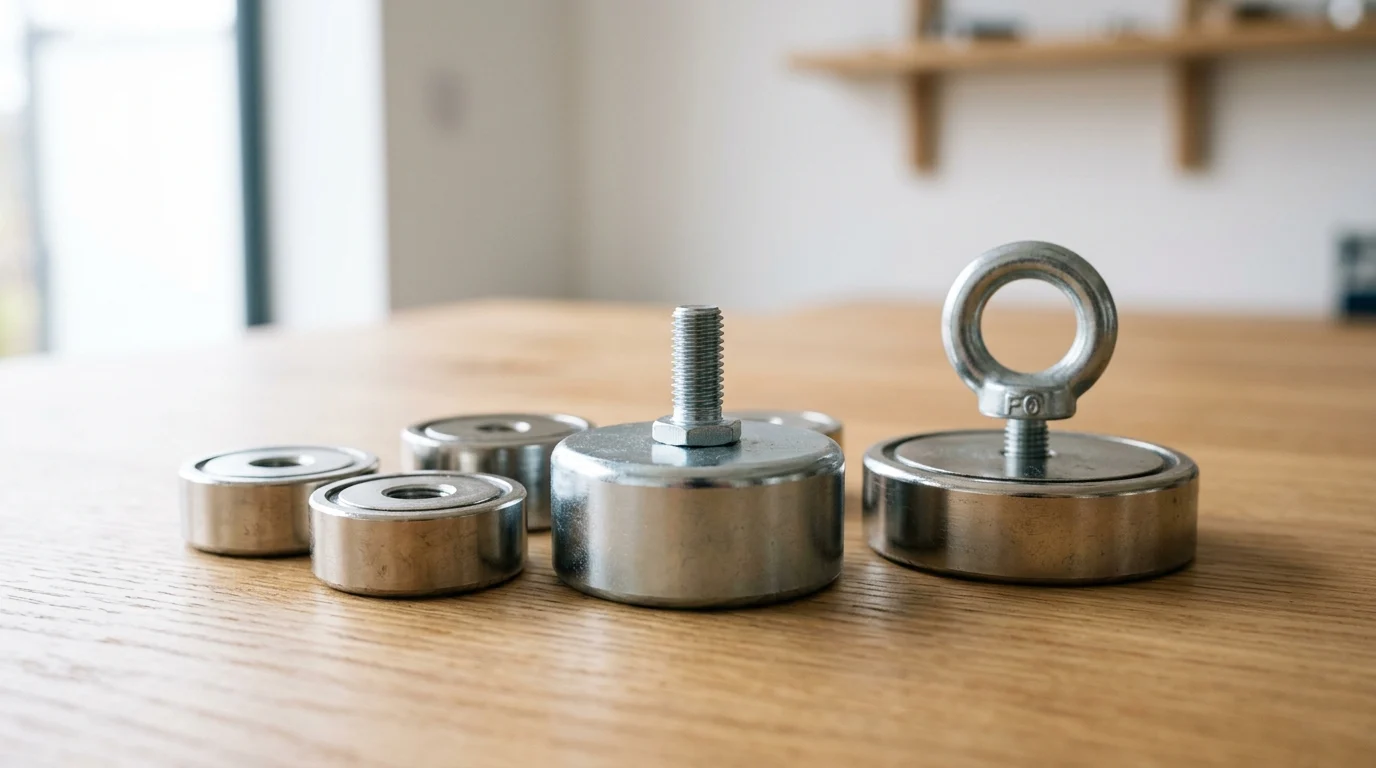
How Pot Magnets Create Value in Manufacturing
Pot magnets represent a highly specialized category of magnetic assemblies designed to maximize holding force within a compact footprint. By encasing a permanent magnet inside a steel shell or "pot," magnetic flux lines are manipulated to concentrate entirely on a single active face. This focused magnetic circuit effectively neutralizes the non-working sides of the magnet and amplifies the perpendicular pull force by up to 300% compared to a bare magnet of identical volume.
In modern manufacturing facilities, this architectural advantage translates directly to operational efficiency. The steel casing not only redirects the magnetic field but also provides critical mechanical protection. Permanent magnet materials, particularly rare-earth variants, are inherently brittle and prone to chipping or cracking under mechanical stress. The steel housing absorbs impact forces and allows for integrated mounting solutions, such as threaded holes or studs, making these devices foundational components in industrial automation, tooling, and material handling.
Why Pot Magnets Are More Than Holding Devices
The utility of pot magnets extends far beyond simple fastening. In lean manufacturing environments, engineers leverage these assemblies to execute Single-Minute Exchange of Die (SMED) principles. By replacing traditional bolted fixtures with high-strength pot magnets, facilities frequently reduce equipment changeover times from standard 45-minute intervals to under 5 minutes. This rapid interchangeability minimizes machine downtime and enables highly flexible production lines capable of accommodating low-volume, high-mix manufacturing schedules.
Furthermore, the steel cup provides a robust chassis for integration into complex machinery. Unlike bare magnets that require specialized adhesives or delicate clamping mechanisms, pot magnets can be torqued directly into structural frameworks. This mechanical integration allows manufacturers to deploy magnetic holding forces in high-vibration environments, such as stamping presses or continuous motion conveyor systems, without risking catastrophic magnet failure or detachment.
Key Performance Terms Engineers Should Define
To properly specify pot magnets, engineering teams must look beyond arbitrary "strength" labels and define precise performance metrics. The primary metric is perpendicular pull force, which is the maximum theoretical resistance a magnet provides when pulled straight off a thick, unpainted, flat steel plate. However, engineers must also account for shear load capacity. Because steel-on-steel friction is relatively low, a standard pot magnet will typically begin to slide parallel to the surface at just 20% to 30% of its rated perpendicular pull force.
Operating temperature is another critical boundary condition that must be defined during the specification phase. Standard Neodymium (NdFeB) N35 pot magnets suffer irreversible flux loss if exposed to temperatures exceeding 80°C (176°F). For high-temperature manufacturing environments like injection molding or automated welding cells, engineers must specify higher-grade NdFeB variants (rated up to 150°C), Samarium Cobalt (SmCo) assemblies capable of withstanding 300°C, or Alnico variants that remain stable up to 500°C.
Common Manufacturing Applications for Pot Magnets
Across the factory floor, the concentrated holding power and mechanical versatility of pot magnets are deployed to solve specific operational challenges. While their applications are incredibly diverse, they generally fall into distinct categories that drive safety, precision, and throughput. Understanding these deployment methods allows process engineers to identify new opportunities for magnetic integration within their own facilities.
From rigid machining centers to dynamic robotic arms, pot magnets serve as temporary yet intensely secure coupling agents. Their ability to deliver immediate, reversible clamping force without requiring pneumatics, hydraulics, or electrical power makes them indispensable for streamlining complex manufacturing workflows.
Workholding and Fixturing
In precision machining and assembly, maintaining tight tolerances requires absolute workpiece stability. Pot magnets are frequently integrated into custom workholding jigs and fixtures to secure ferromagnetic parts during drilling, tapping, or automated inspection. By utilizing arrays of internal-threaded pot magnets, toolmakers can build modular fixture plates that hold steel blanks with tolerances as tight as +/- 0.05mm.
For heavy-duty applications such as welding fabrication, specialized pot magnets with V-grooved faces or articulating arms are used to hold steel plates precisely at 90-degree or 45-degree angles. Typical holding forces for these workholding applications range from 50 kg for localized edge alignment to over 200 kg per unit for securing heavy structural beams during initial tack welding.
Material Handling and Retrieval
Automated material handling relies heavily on predictable, instantaneous gripping mechanisms. Pot magnets are a staple in End-of-Arm Tooling (EOAT) for pick-and-place robots handling sheet metal, automotive body panels, and stamped steel components. Unlike vacuum grippers, which can fail due to porous surfaces or oily residues, magnetic handling provides a positive lock regardless of surface contamination.
When lifting components, engineering standards dictate strict safety protocols. A standard requirement in overhead material handling is a 3:1 safety factor. Therefore, if a robotic cell is tasked with moving a 50 kg steel engine block, the collective pot magnet array must possess a minimum rated perpendicular pull force of 150 kg. This buffer accounts for acceleration forces, emergency stops, and minor surface imperfections that degrade magnetic coupling.
Machine Guarding and Inspection
Safety and quality assurance protocols frequently utilize pot magnets for non-permanent installations. Machine guarding panels, which must be routinely removed for maintenance, are often secured using high-strength pot magnets rather than captive screws. To comply with machine safety standards such as ISO 14120, these magnetic interlocks must require intentional, significant force to remove—often engineered to exceed 200 Newtons of dislodgment force per attachment point.
In quality control departments, inspectors use pot magnets equipped with articulating arms to mount dial indicators, laser trackers, and coordinate measuring machine (CMM) reference spheres directly onto machine beds or large castings. The rigid steel housing of the magnet ensures that no mechanical deflection occurs during micrometer-level measurements, guaranteeing the integrity of the inspection data.
How to Compare Pot Magnet Designs and Ratings
Selecting the optimal pot magnet requires a comparative analysis of mechanical architectures, environmental conditions, and raw material properties. Because the performance of a magnetic assembly is highly sensitive to the physical parameters of its environment, relying solely on manufacturer-provided "maximum pull force" ratings can lead to catastrophic system failures.
Design engineers must evaluate the specific interface requirements of the application, the nature of the mating surface, and the thermal and chemical exposures the magnet will endure. By systematically comparing these variables, procurement and engineering teams can specify assemblies that deliver reliable, repeatable performance.
Common Pot Magnet Designs
Pot magnets are manufactured in several standardized mechanical configurations to accommodate different mounting strategies. Countersunk pot magnets feature a central conical hole, allowing them to be fastened flush to a surface using standard flat-head machine screws. Through-hole designs utilize a straight cylindrical bore for socket-head cap screws, ideal for applications requiring high torque during installation.
For integration into threaded assemblies, internal threaded (female) and external threaded stud (male) pot magnets are utilized. These designs range in diameter from miniature 10mm units used in sensor mounting to massive 120mm assemblies deployed in heavy rigging. The choice of design dictates the structural integrity of the mount; for instance, external threaded studs are preferred when the magnet must act as a rigid standoff in a custom fixture.
Pull Force, Shear Load, Air Gap, and Surface Conditions
The rated pull force of a pot magnet assumes ideal conditions: a direct, perpendicular pull against a thick, flat, machined steel plate. In reality, manufacturing environments introduce variables that severely degrade this performance. The most critical factor is the air gap—any non-magnetic space between the magnet and the target surface, including paint, rust, plating, or literal air.
Due to the inverse-square law governing magnetic fields, even microscopic air gaps cause exponential force reduction. A mere 1mm air gap (caused by heavy industrial powder coating or rough surface scaling) can reduce the effective pull force by 50% to 70%. Furthermore, surface roughness (Ra) diminishes the contact area. Engineers must derate the expected holding force when dealing with rough castings or thin sheet metal, as thin materials become magnetically saturated and cannot absorb the full flux of the pot magnet.
Neodymium, Ferrite, and Other Magnet Material Choices
The internal permanent magnet material dictates the assembly's baseline strength, thermal tolerance, and cost. Neodymium (NdFeB) is the standard for high-strength applications, offering the highest energy product but remaining vulnerable to high heat and corrosion. Ferrite (Ceramic) magnets are highly cost-effective and inherently corrosion-resistant, making them ideal for submerged or outdoor applications, though they possess only a fraction of Neodymium's strength.
| Magnetic Material | Max Operating Temp | Relative Pull Force | Corrosion Resistance | Cost Profile |
|---|---|---|---|---|
| Neodymium (NdFeB) | 80°C to 150°C | Highest (100%) | Low (Requires Coating) | High |
| Ferrite (Ceramic) | 250°C | Low (15 - 20%) | Excellent | Lowest |
| Samarium Cobalt (SmCo) | 300°C to 350°C | High (80%) | Good | Very High |
| Alnico | 500°C to 550°C | Moderate (30%) | Good | Moderate |
When comparing these materials, the operating environment must drive the decision. A heavy-duty robotic welding cell operating near 200°C will quickly demagnetize a standard Neodymium pot magnet, necessitating the specification of Samarium Cobalt despite its significantly higher raw material cost.
Installation and Maintenance Best Practices
Even the highest-quality pot magnets will fail if subjected to improper installation techniques or neglected maintenance schedules. The physical forces generated by these assemblies, combined with the brittle nature of permanent magnets, require strict adherence to mechanical best practices.
Implementing standardized procedures for validation, mounting, and lifecycle management ensures that magnetic assemblies perform safely over their expected operational lifespan, which can easily exceed a decade under optimal conditions.
Validating Pot Magnets Before Production Use
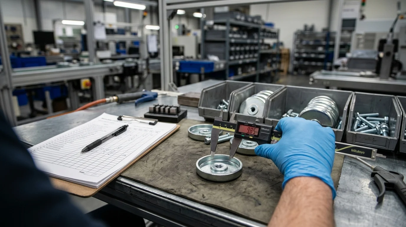
Before integrating pot magnets into active production lines, facilities must conduct rigorous empirical validation. Relying on theoretical datasheets is insufficient due to the unique surface conditions of specific workpieces. Engineers should utilize digital dynamometers to perform localized pull-off tests on the actual materials being handled.
This validation process establishes a baseline breakaway force for the specific application. For lateral holding applications, engineers must physically measure the shear force required to induce slippage. If a pot magnet is rated for 100 kg of perpendicular pull, validation testing on a specific oiled steel component might reveal a shear slippage point of just 15 kg. Documenting these real-world metrics is critical for programming robotic acceleration limits and designing fail-safe mechanisms.
Installation Practices That Prevent Slippage and Damage
Improper torque application during installation is a leading cause of pot magnet failure. When securing an internal threaded pot magnet, exceeding the manufacturer's maximum torque specifications can warp the steel shell, cracking the internal rare-earth magnet. For example, a standard M6 threaded stud pot magnet typically carries a maximum torque rating of just 5 to 7 Nm. Utilizing calibrated torque wrenches is mandatory to prevent structural damage.
To combat the inherent vulnerability of shear slippage, facilities employ specific installation enhancements. Applying custom polyurethane coatings or fitting the pot magnet with a rubber boot dramatically increases the friction coefficient between the magnet and the workpiece. This simple modification can elevate the shear load capacity from a baseline of 20% to as high as 40% or 50% of the perpendicular pull force, while simultaneously protecting delicate workpiece surfaces from scratching.
Inspection, Cleaning, Tracking, and Replacement
Magnetic assemblies naturally attract ferrous debris, commonly referred to as swarf. In machining environments, the accumulation of swarf across the active face of the pot magnet acts as an artificial air gap, steadily degrading holding power. Maintenance protocols must mandate regular cleaning using specialized non-magnetic scrapers or compressed air (with appropriate safety shielding) to keep the magnetic circuit clear.
Permanent magnets lose a negligible amount of baseline flux over time—typically less than 1% per decade for NdFeB materials under normal conditions. However, repeated physical impacts or exposure to stray demagnetizing fields can accelerate degradation. Facilities should implement an annual calibration check, utilizing a gaussmeter or a standardized pull-test jig, to verify that deployed pot magnets still meet the minimum required safety thresholds. Units falling below 90% of their baseline performance should be immediately tagged and replaced.
How Buyers Choose Reliable Pot Magnets
Procuring pot magnets for industrial applications requires a strategic approach that balances initial capital expenditure against long-term operational reliability. Buyers must navigate a global supply chain characterized by wildly varying quality control standards and raw material purity levels.
Successful procurement involves scrutinizing supplier certifications, understanding the true cost of operational downtime, and ensuring that the final purchased assembly precisely matches the engineering specifications mandated by the facility.
Sourcing and Compliance Requirements
Industrial buyers must demand strict compliance documentation from magnet suppliers. Because Neodymium magnets are highly susceptible to oxidation, the quality of the protective plating (typically a Ni-Cu-Ni triple layer or heavy Zinc coating) is paramount. Buyers should require RoHS (Restriction of Hazardous Substances) and REACH compliance certificates to ensure coatings are free from restricted heavy metals.
Furthermore, sourcing partners must possess ISO 9001 certification or equivalent quality management credentials. This ensures traceability of the rare-earth elements used in the magnetic core. Counterfeit or highly diluted NdFeB materials are common in the secondary market; these sub-standard magnets may initially present strong magnetic fields but will suffer rapid, irreversible flux loss under moderate thermal or mechanical stress.
Comparing Total Cost of Ownership
Evaluating pot magnets based solely on initial unit cost is a flawed procurement strategy. The Total Cost of Ownership (TCO) must account for replacement frequency, maintenance requirements, and the financial impact of catastrophic holding failures.
| Cost Variable | Economy Ferrite Pot Magnet | Premium Coated NdFeB Pot Magnet |
|---|---|---|
| Initial Unit Cost | $4.50 | $18.00 |
| Annual Replacement Rate | 4 units (due to impact breakage) | 1 unit (high durability) |
| Footprint / Size Requirement | Large (100mm diameter) | Compact (32mm diameter) |
| Estimated 5-Year TCO (per node) | $90.00 + High Downtime Risk | $90.00 + Minimal Downtime Risk |
While a premium Neodymium assembly may command a 300% to 400% price premium over a comparable Ferrite unit, its compact footprint allows for more efficient tooling design. Moreover, the enhanced holding security drastically reduces the risk of dropped payloads or fixture shifts, which can result in thousands of dollars in scrapped parts or damaged machinery.
Matching Pot Magnets to the Application
Ultimately, reliable procurement relies on a tight feedback loop between purchasing agents and facility engineers. Buyers must verify that the specified Minimum Order Quantities (MOQs) align with maintenance replacement schedules. Standard off-the-shelf pot magnets frequently have low MOQs, but custom assemblies with specific thread pitches or specialized high-temperature epoxies typically require MOQs ranging from 500 to 1,000 units.
By cross-referencing the application's thermal requirements, shear load demands, and environmental hazards with the supplier's verified capabilities, buyers can transition pot magnets from disposable commodities into reliable, high-performance manufacturing assets. This precise alignment of operational needs with procurement standards guarantees maximum return on investment for magnetic tooling infrastructure.
Key Takeaways
- The most important conclusions and rationale for Pot Magnets
- Specs, compliance, and risk checks worth validating before you commit
- Practical next steps and caveats readers can apply immediately
Frequently Asked Questions
What should buyers compare first when sourcing Pot Magnets?
Start with airflow/spec range, compliance requirements, installation constraints, and after-sales spare-part policy. These four factors usually determine total risk and margin quality.
How can readers control landed cost for Pot Magnets?
Break down unit FOB, packaging volume, container utilization, duty/tax, and expected return rate. A simple landed-cost model by SKU tier helps avoid margin surprises.
Which certifications are commonly required for Pot Magnets in key markets?
Requirements vary by destination market; verify applicable electrical/safety and material compliance standards before PO confirmation, and keep lab reports tied to exact SKU versions.
How should distributors set MOQ and inventory targets for Pot Magnets?
Use channel demand split and lead time to set tiered MOQ. Keep fast-moving SKUs deeper in stock while limiting long-tail variants with slower turns and higher holding costs.
What is a practical quality-control checklist for Pot Magnets orders?
Define AQL, critical defect list, function tests, and packaging drop checks. Run pre-shipment inspection and keep a traceable defect feedback loop with the factory.