 EN
EN AR
AR HR
HR CS
CS DA
DA NL
NL FI
FI FR
FR DE
DE EL
EL IT
IT JA
JA KO
KO NO
NO PL
PL PT
PT RU
RU ES
ES SV
SV IW
IW VI
VI TH
TH TR
TR FA
FA MS
MS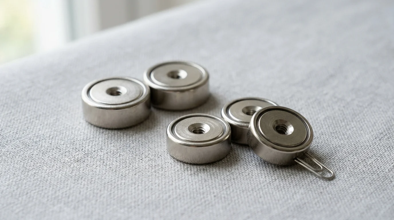
In precision manufacturing, a holding point only a few millimeters wide can determine whether a part seats correctly, a robot cycle repeats accurately, or a fixture drifts out of tolerance. Small pot magnets solve this challenge by combining a permanent magnet with a machined steel cup that focuses magnetic force onto one active face. The result is compact, zero-energy holding with surprisingly high pull strength and stable mounting options for jigs, CNC fixtures, inspection stations, and automated tooling. This article explains how their construction improves force concentration, why they support repeatable positioning, and which specifications engineers should evaluate when choosing a compact magnetic holding solution.
How Small Pot Magnets Improve Precision Holding
Small pot magnets, typically ranging from 10mm to 50mm in diameter, have become fundamental components in industrial precision holding, fixturing, and automation systems. Unlike bare magnets, which project magnetic fields in multiple directions, pot magnets consist of a permanent magnet encased in a precision-machined steel shell or cup. This structural integration fundamentally alters the magnetic circuit, transforming a standard magnet into a highly directional, high-performance holding device.
In modern manufacturing environments, where tolerances are frequently measured in hundredths of a millimeter, the ability to secure components rapidly and reliably is paramount. Small pot magnets bridge the gap between permanent mechanical fastening and temporary clamping, offering a zero-energy holding solution capable of exerting hundreds of Newtons of force within a highly compact footprint. By leveraging sophisticated magnetic materials and optimized cup geometries, these assemblies provide engineers with a versatile tool for enhancing operational precision.
Why they support repeatable positioning
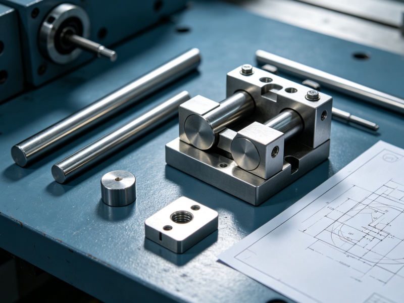
Repeatable positioning is a critical requirement in automated assembly lines, robotic end-of-arm tooling, and CNC machining fixtures. Small pot magnets support this repeatability by combining magnetic adhesion with highly precise mechanical mounting interfaces. The steel cup surrounding the magnet provides a rigid, dimensionally stable surface that can be machined to exacting tolerances, often within ±0.05mm of the specified diameter and height.
Because the steel shell features standardized mounting options—such as threaded studs, internal tapped holes, or countersunk through-holes—engineers can integrate these magnets directly into rigid jigs and fixtures. When a ferromagnetic workpiece is introduced to the fixture, the pot magnet draws it firmly against a known datum plane. In automated systems, this ensures that the workpiece seats in the exact same orientation during every cycle. This setup can reliably achieve positional repeatability metrics within 0.02mm—a level of precision difficult to maintain with mechanical clamps that are subject to wear and variable actuation forces.
How their construction concentrates holding force
The defining functional advantage of a pot magnet lies in its magnetic circuit architecture. In a standard bare magnet, the magnetic flux lines travel from the north pole to the south pole through the surrounding air, resulting in a diffuse field that wastes a significant portion of its potential holding energy. The steel cup in a pot magnet acts as a highly permeable flux conductor, capturing the magnetic field from one pole and redirecting it to the open face of the assembly.
By forcing both the north and south poles to act on the same active gripping surface, the steel shell concentrates the magnetic flux lines into a dense, shallow field. This concentration dramatically increases the localized holding force, often yielding a 30% to 50% increase in direct pull strength compared to a bare magnet of the exact same volume. For example, a standard 16mm diameter neodymium pot magnet can generate over 140 Newtons of holding force, making it possible to secure heavy components using exceptionally small points of contact.
Key Specifications for Holding Performance
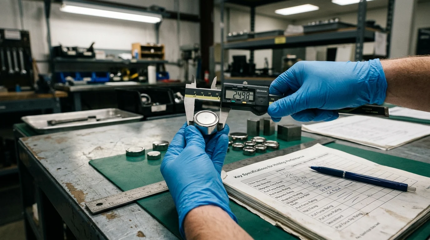
Specifying the correct small pot magnet requires moving beyond basic dimensional requirements to evaluate the nuanced interplay of magnetic forces and environmental conditions. Industrial applications rarely present perfect holding scenarios; surface irregularities, lateral forces, and thermal fluctuations constantly challenge theoretical magnetic capabilities. Engineers must carefully analyze a specific set of performance specifications to ensure the chosen magnet will function reliably under real-world operational stresses.
How pull force, shear load, and air gap affect grip
The distinction between direct pull force and shear load is often the most critical factor in specifying a small pot magnet. Direct pull force represents the maximum resistance the magnet offers when pulled perfectly perpendicular to a thick, flat, machined steel surface. However, when mounted vertically, the magnet is subjected to shear load—the force acting parallel to the gripping surface. Due to the relatively low coefficient of friction between steel and standard magnet coatings (typically around 0.15 to 0.20), the shear force capacity of a pot magnet is generally only 15% to 20% of its rated direct pull force.
Furthermore, holding performance is highly sensitive to the introduction of an air gap between the magnet's active face and the target material. Because a pot magnet's concentrated magnetic field is exceptionally shallow, even minor separations cause an exponential drop in holding force. A seemingly negligible air gap of just 0.5mm—whether caused by paint, rust, uneven surfaces, or non-magnetic plating—can reduce the effective pull force by more than 50%. Engineers must account for expected surface finishes and coatings on the workpiece when calculating the required baseline pull strength.
How material, cup geometry, coating, and temperature matter
Material selection dictates both environmental resilience and magnetic strength. Neodymium (NdFeB) offers the highest energy product, ideal for maximizing grip in confined spaces, but standard grades suffer irreversible demagnetization at temperatures exceeding 80°C. For high-temperature environments, Samarium Cobalt (SmCo) provides excellent stability up to 350°C, while traditional Ceramic (Ferrite) magnets, though bulkier, offer cost-effective performance up to 250°C with inherent corrosion resistance.
Cup geometry and protective coatings further influence operational reliability. A standard nickel-copper-nickel (Ni-Cu-Ni) electroplating, typically 15 to 25 microns thick, protects NdFeB magnets from rapid oxidation but offers minimal friction. To combat the severe reduction in shear load capacity, engineers often specify rubber-coated pot magnets. A Santoprene or polyurethane jacket increases the coefficient of friction to approximately 0.60, significantly boosting shear resistance while simultaneously protecting delicate workpieces from scratching. However, this comes at the cost of introducing a permanent, slight air gap.
Which specification table engineers should use
To streamline the specification process, engineers rely on standardized performance matrices to compare baseline characteristics before applying application-specific safety factors. The table below illustrates the critical specifications for a standard 25mm diameter pot magnet across different core materials, providing a comparative baseline for initial engineering calculations.
| Specification | NdFeB (Grade N35) | SmCo (Grade Sm2Co17) | Ferrite (Grade Y30) |
|---|---|---|---|
| Max Operating Temperature | 80°C | 350°C | 250°C |
| Typical Pull Force (25mm dia) | ~220 N | ~150 N | ~40 N |
| Shear Load Capacity (Steel on Steel) | ~44 N | ~30 N | ~8 N |
| Inherent Corrosion Resistance | Low (Requires Coating) | High | Very High |
| Magnetic Field Depth | Very Shallow | Shallow | Deep |
By cross-referencing this data with the mechanical demands of the application, design teams can quickly eliminate unsuitable materials. For instance, an application requiring 100 N of holding force in a 150°C environment immediately rules out standard NdFeB due to thermal constraints, directing the engineer toward a SmCo solution despite the higher material cost.
Small Pot Magnets vs Other Holding Methods
While small pot magnets offer significant advantages, industrial holding applications frequently pit them against mechanical clamps, industrial adhesives, and pneumatic vacuum systems. Each methodology possesses distinct operational characteristics regarding energy consumption, cycle times, and spatial requirements. Selecting the optimal holding method requires an objective analysis of where magnetic solutions excel and where their inherent limitations necessitate an alternative approach.
When they outperform clamps, adhesives, and vacuum
In high-speed automation, actuation time is paramount. Small pot magnets require zero milliseconds to actuate; their holding force is continuously active, instantly securing a ferromagnetic part upon contact. Conversely, pneumatic vacuum cups require 50 to 200 milliseconds to evacuate air and establish a grip, while mechanical toggle clamps or pneumatic cylinders can require upwards of 500 milliseconds to physically deploy and lock into position.
Furthermore, pot magnets outclass structural adhesives in applications requiring temporary or dynamic fixturing. Adhesives provide immense shear and tensile strength but require curing times ranging from minutes to 24 hours, rendering them useless for rapid cycle manufacturing. Magnets also outperform vacuum systems in environments dealing with porous materials or perforated surfaces, where maintaining the necessary -0.8 bar of vacuum pressure is impossible due to constant air leakage.
What trade-offs affect precision and release speed
Despite their advantages, magnetic holding systems present specific engineering trade-offs, primarily concerning precision maintenance and release mechanics. Because pot magnets are continuously active, they inherently attract ferromagnetic debris, such as machining swarf or grinding dust. The accumulation of debris on the magnet's face introduces an unintended air gap, degrading holding force and destroying positional accuracy. In environments with heavy particulate contamination, mechanical clamps often provide more reliable long-term precision.
Release speed is another critical trade-off. While gripping is instantaneous, releasing a part held by a 300-Newton pot magnet requires significant mechanical intervention. Automation systems must incorporate pneumatic push-off pins, cam levers, or sliding shear mechanisms to break the magnetic circuit. This requirement can complicate end-of-arm tooling designs, whereas a vacuum system simply vents to the atmosphere to drop a part instantly.
Where neodymium and ferrite pot magnets fit best
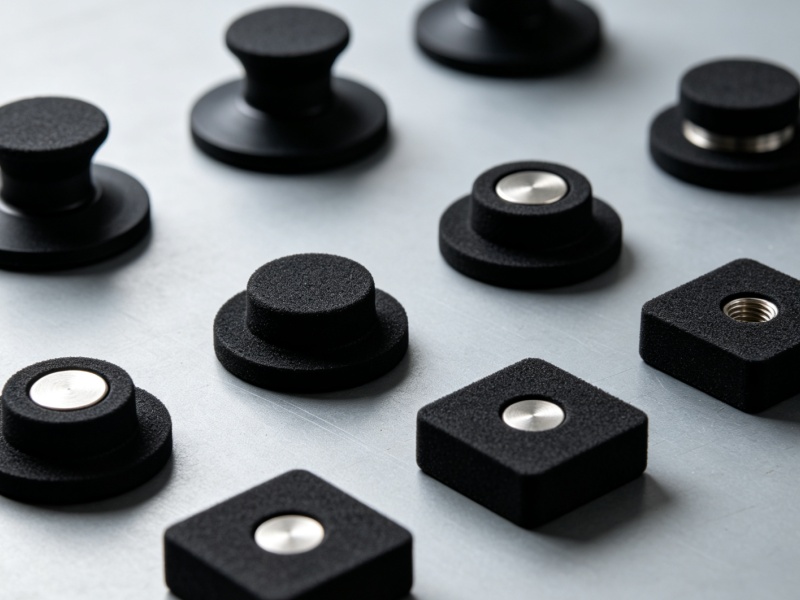
When a magnetic solution is selected, the choice typically narrows down to neodymium (NdFeB) or ferrite compositions. Neodymium is the undisputed choice for applications restricted by spatial constraints. A compact 10mm NdFeB pot magnet can easily generate 25 Newtons of pull force, allowing for discreet integration into tight tooling clearances or miniature sensor housings.
Ferrite pot magnets, conversely, are favored in cost-sensitive, larger-scale applications where spatial constraints are relaxed. To achieve the same 25 Newtons of force, a ferrite pot magnet might require a 20mm or 25mm diameter. However, ferrite excels in high-temperature environments (up to 250°C) and corrosive atmospheres without the need for expensive platings.
| Holding Method | Actuation Time | Energy Required | Maintenance Level | Typical Holding Force (25mm footprint) |
|---|---|---|---|---|
| Small Pot Magnet (NdFeB) | 0 ms (Always On) | Zero | Low | 220 N |
| Pneumatic Vacuum Cup | 50-200 ms | Continuous Air | Medium | ~45 N (at -0.8 bar) |
| Mechanical Toggle Clamp | 500+ ms | Manual/Pneumatic | Medium | 500+ N |
| Structural Adhesive | 2-24 hours | Zero | High (Permanent) | >1000 N |
Selection, Installation, and Testing Practices
The theoretical holding force of a small pot magnet is only as reliable as its physical integration into the broader assembly. Proper selection must be followed by rigorous engineering practices regarding load calculations, installation torque, and empirical validation. Failure to respect the mechanical limitations of the magnet and its steel shell frequently leads to premature failure, cracked components, or catastrophic loss of holding power during operation.
How to calculate safety factors and load orientation
Establishing appropriate safety factors requires a comprehensive understanding of the load profile and operational environment. Relying solely on the manufacturer's maximum pull force rating is a dangerous engineering practice, as these ratings are generated under ideal laboratory conditions. For static, perpendicular loads operating in clean environments, engineers should apply a minimum safety factor of 2:1. If the required holding force is 50 N, specify a magnet rated for at least 100 N.
For dynamic loads, or applications subjected to vibration, acceleration, and shear forces, the safety factor must be increased significantly. A safety factor of 3:1 or 4:1 is standard for robotic end-of-arm tooling, where the rapid deceleration of a robotic arm multiplies the effective mass of the payload. When calculating load orientation, designers must prioritize mechanical support for shear loads—using a shallow physical ledge or locating pin to bear the weight of the part, allowing the magnet to perform solely the direct pull function it is best suited for.
Which installation practices improve repeatability
Installation methodologies directly influence both the longevity of the magnetic assembly and the repeatability of the fixture. When utilizing countersunk pot magnets, over-tightening the mounting screw is a primary cause of failure. The sintered magnetic material inside the steel cup is highly brittle; excessive torque will cause the magnet to fracture, degrading its magnetic field and generating loose debris. Engineers must strictly enforce torque limits during assembly, typically capping torque at 2.0 to 2.5 Nm for an M4 countersunk screw.
To maintain positional accuracy over thousands of cycles, the mounting hardware must resist vibrational loosening without relying on excessive torque. The application of medium-strength thread-locking compounds (such as Loctite 242) is highly recommended. Furthermore, when pressing cylindrical pot magnets into blind holes, an interference fit should be avoided, as radial compression can distort the thin steel shell. Instead, engineers should utilize a transition fit (e.g., H7/g6 tolerances) secured with industrial retaining compounds.
How to verify pull force during prototyping
Theoretical calculations must be validated through rigorous prototyping and empirical testing before moving to full-scale production. Because magnetic saturation depends heavily on the thickness of the target material, testing must be conducted using the exact grade and thickness of steel that will be used in the final application. A pot magnet rated for 200 N on a 10mm-thick steel plate may only generate 80 N on a 1mm-thick sheet of the same material, as the thin sheet cannot fully absorb the magnetic flux.
Prototyping verification should involve the use of digital force gauges or tensile testing machines to establish a baseline pull force curve. Engineers should intentionally introduce anticipated variables during this testing phase—such as inserting 0.1mm to 0.5mm plastic shims to simulate paint thickness or surface contamination. By plotting the degradation of pull force against a known air gap, the engineering team can accurately define the operational limits of the fixture and certify that the assembly meets the mandated safety factors under worst-case scenarios.
How Industrial Buyers Should Decide
Procuring small pot magnets for industrial applications extends beyond matching technical specifications in a catalog. Buyers must navigate a complex supply chain heavily reliant on raw material availability, strict quality control standards, and geopolitical pricing dynamics. Industrial buyers must adopt a holistic approach to procurement, evaluating potential suppliers based on their manufacturing capabilities, compliance certifications, and total lifecycle cost rather than merely the lowest initial unit price.
Which sourcing, quality, and compliance factors matter
Quality assurance in magnetic assemblies requires stringent supplier validation. Variations in the sintering process or the use of lower-grade raw materials can result in significant batch-to-batch inconsistencies in magnetic strength. Industrial buyers should require suppliers to maintain ISO 9001 certification and provide comprehensive magnetic testing reports, including B-H curve documentation for the raw materials used. A reliable supplier should guarantee a defect rate of fewer than 50 Parts Per Million (PPM) for critical dimensions and pull force variances.
Environmental compliance is equally critical, particularly regarding the coatings applied to the steel shell and the magnet itself. Buyers must ensure that all supplied components strictly adhere to RoHS (Restriction of Hazardous Substances) and REACH directives. This is especially relevant when sourcing zinc or nickel-plated pot magnets, as legacy manufacturing processes often utilized hexavalent chromium, a highly restricted substance. Furthermore, for applications exposed to moisture, buyers should specify validated salt spray test performance, demanding a minimum of 48 to 96 hours of resistance for standard Ni-Cu-Ni platings.
How to assess lifecycle cost, supplier capability, and lead time
Evaluating the total lifecycle cost of small pot magnets requires looking past the initial unit price to account for assembly efficiency and operational longevity. While a bare neodymium magnet might cost $0.50 and a comparable pot magnet assembly costs $0.80, the pre-engineered mounting features of the pot magnet can save upwards of $2.00 in labor and custom machining costs per unit during assembly. Furthermore, the steel shell's protection against mechanical impact drastically reduces the frequency of replacement, driving down long-term maintenance expenditures.
Supplier capability and lead times must align with production schedules. Off-the-shelf standard pot magnets are typically available with lead times of just a few days, making them ideal for rapid prototyping. However, industrial buyers specifying custom geometries, specialized high-temperature resins, or specific threading requirements should anticipate lead times ranging from 4 to 8 weeks. Additionally, custom runs generally require Minimum Order Quantities (MOQs) ranging from 1,000 to 5,000 units to offset the costs of bespoke tooling and specialized magnetization fixtures. Establishing long-term supply agreements with manufacturers capable of holding buffer stock is the most effective strategy to mitigate these lead time risks and ensure uninterrupted production.
Key Takeaways
- Select small pot magnets in the 10 mm to 50 mm range when a compact, zero-energy holding point is needed for fixtures, tooling, or automation.
- Use pot magnets instead of bare magnets when higher localized grip is required, because the steel cup can improve direct pull strength by about 30% to 50%.
- Specify accurate mounting styles such as threaded studs, internal tapped holes, countersunk holes, or straight holes to integrate magnets into repeatable fixture designs.
- Design the holding surface around a known datum plane, since properly mounted small pot magnets can support positioning repeatability of about 0.02 mm in controlled systems.
- Match magnet size, material, coating, and pull force to the application, as a 16 mm neodymium pot magnet can generate more than 140 N of holding force under ideal contact conditions.
Frequently Asked Questions
What are small pot magnets used for in industrial applications?
Small pot magnets are used for precision holding, fixturing, positioning, inspection setups, robotic tooling, signage, and temporary workholding where compact size and repeatable magnetic grip are needed.
Why are pot magnets stronger than bare magnets of similar size?
A steel cup redirects and concentrates magnetic flux onto the active face, reducing wasted field dispersion. This can increase direct pull strength by about 30% to 50% compared with a bare magnet of the same volume.
What sizes are considered small pot magnets?
Small pot magnets are commonly around 10 mm to 50 mm in diameter, depending on the application, pull-force requirement, and mounting style.
Can small pot magnets improve repeatable positioning?
Yes. When integrated into rigid fixtures with accurate mounting interfaces, small pot magnets can help seat ferromagnetic parts against a known datum and support repeatability as tight as about 0.02 mm in controlled setups.
What mounting options are available for small pot magnets?
Common options include threaded studs, internal tapped holes, countersunk holes, straight holes, and specialty housings such as brass pot magnets, depending on the fixture or equipment design.