 EN
EN AR
AR HR
HR CS
CS DA
DA NL
NL FI
FI FR
FR DE
DE EL
EL IT
IT JA
JA KO
KO NO
NO PL
PL PT
PT RU
RU ES
ES SV
SV IW
IW VI
VI TH
TH TR
TR FA
FA MS
MS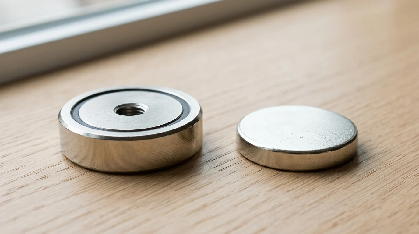
In industrial holding, fixturing, recovery, and equipment mounting, the best magnet is not always the strongest raw magnet on paper. The way magnetic flux is controlled, protected, and mechanically mounted can decide whether a system performs safely or fails under load. Pot magnets use a steel cup to concentrate force onto one working face, while bare magnets offer a more open field for custom designs. This article compares their structure, magnetic circuit behavior, installation options, durability, and ideal use cases so engineers, buyers, and workshop users can specify the right solution with fewer performance surprises and lower lifecycle risk.
Why the Pot Magnet vs Regular Magnet Choice Matters
Selecting the correct magnetic assembly for industrial applications extends far beyond specifying material grades. Engineers and procurement specialists frequently face the decision between utilizing standard, bare magnets and integrated pot magnets. This choice fundamentally dictates the efficiency of the magnetic circuit, the mechanical durability of the installation, and the overall lifecycle cost of the assembly.
Understanding the structural and operational disparities between these two architectures is the critical first step in optimizing any fixturing, sensing, or lifting system. A misaligned specification can lead to catastrophic mechanical failures, excessive material costs, or insufficient actuation forces under operational loads.
What Defines a Pot Magnet
A pot magnet is an engineered assembly consisting of a permanent magnet encased within a steel shell or cup. This steel casing is not merely a protective enclosure; it acts as an active component of the magnetic circuit. By directing the magnetic flux lines originating from the concealed pole and routing them to the open face, the steel housing concentrates the magnetic energy onto a single active surface.
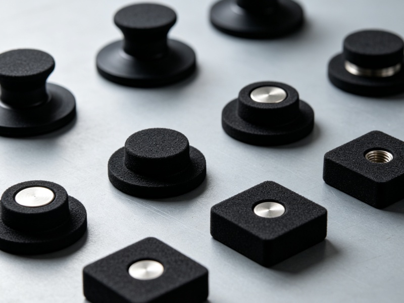
Commercially, these assemblies are available in standard diameters ranging from 10mm up to 120mm, utilizing core materials such as Neodymium (NdFeB), Samarium Cobalt (SmCo), or Ferrite, depending on thermal and cost constraints. The integration of the steel cup also facilitates immediate mechanical mounting options, incorporating features like threaded holes, countersinks, or protruding studs directly into the structural housing.
What Defines a Regular Magnet
Conversely, a regular magnet—often referred to as a bare or raw magnet—is a standalone piece of magnetic material machined into geometries such as discs, blocks, rings, or cylinders. Unlike pot magnets, regular magnets emit magnetic flux freely from both their North and South poles, creating a symmetrical, three-dimensional magnetic field that extends deeply into the surrounding air.
Without a steel housing to alter or restrict the flux path, regular magnets interact with ferrous materials or other magnets on multiple faces simultaneously. While they lack the built-in mechanical protection of a steel shell, their unconstrained field makes them highly versatile for integration into custom housings, over-molded plastics, or applications requiring specific diametrical or multipole magnetization patterns.
How Magnetic Circuit Design Affects Performance
The presence or absence of the steel casing fundamentally alters the magnetic circuit design, yielding vastly different performance profiles. In a regular magnet, the magnetic field lines travel through the air to return to the opposite pole, which creates high reluctance and limits the effective holding force on a single face.
When a regular magnet is inserted into a steel pot, the high-permeability steel provides a low-reluctance path for the magnetic flux. This redirection concentrates the flux density at the working face. Consequently, a pot magnet can generate a localized holding force that is 2 to 4 times greater than a bare magnet of identical volume, provided it is in direct, flush contact with a thick, flat ferrous workpiece. However, this concentrated field has an exceptionally shallow reach, making magnetic circuit design the decisive factor when evaluating the required operational air gap.
Key Performance Differences

To engineer a reliable magnetic system, designers must quantify how pot magnets and regular magnets respond to the physical demands of the application. Performance cannot be evaluated solely on the maximum energy product (MGOe) of the underlying material; it must account for real-world variables such as shear forces, environmental degradation, and spatial constraints.
Holding Force, Shear Force, and Air Gaps
Holding force, or pull force, represents the maximum perpendicular load a magnet can sustain before detaching from a steel plate. Because of their optimized flux path, Neodymium pot magnets can achieve extraordinary pull forces, often exceeding 100 kg (980 N) for a compact 50mm diameter unit. However, this peak force is highly dependent on a zero-air-gap condition. Even a minimal air gap—introduced by paint, rust, or physical spacing—causes the holding force of a pot magnet to plummet exponentially.
A 2mm air gap can reduce a pot magnet's pull force by over 70%. Regular magnets, possessing a deeper-reaching magnetic field, experience a less drastic percentage drop in holding force across the same air gap. Furthermore, engineers must account for shear force (sliding resistance). For both configurations, the functional shear force is typically only 20% to 30% of the maximum perpendicular pull force, necessitating the use of rubber coatings or friction rings to improve lateral grip.
| Magnet Type | Pull Force at 0mm Air Gap | Pull Force at 2mm Air Gap | Effective Field Depth |
|---|---|---|---|
| 30mm NdFeB Pot Magnet | 350 N | 85 N | Shallow (< 3mm) |
| 30mm NdFeB Regular Disc | 180 N | 110 N | Deep (> 10mm) |
Temperature, Corrosion, and Impact Resistance
Industrial environments routinely expose components to elevated temperatures, corrosive chemicals, and mechanical shock. Bare Neodymium magnets are inherently brittle; a minor impact against a steel surface can cause chipping or catastrophic fracturing, leading to a loss of magnetic mass and potential contamination. The steel shell of a pot magnet absorbs these mechanical impacts, shielding the fragile sintered core.
Thermally, standard N35 grade Neodymium magnets begin to suffer irreversible flux losses at temperatures exceeding 80°C. While high-temperature grades (e.g., N35EH) can push this limit to 200°C, the adhesive used to bond the magnet inside the steel pot may fail before the magnet demagnetizes. For extreme thermal environments up to 300°C, bare Samarium Cobalt (SmCo) magnets or special mechanically retained SmCo pot magnets are required. Corrosion is another critical metric; while bare magnets rely entirely on their 10-20 micron Ni-Cu-Ni plating to prevent oxidation, pot magnets offer an additional layer of steel and epoxy potting. However, the steel housing itself remains susceptible to rust unless manufactured from stainless steel (e.g., 316 grade).
Mounting, Directionality, and Field Control
Integration into industrial machinery relies heavily on mounting methodology and field directionality. Pot magnets are inherently designed for rapid mechanical integration. Standardized configurations include internally threaded studs, threaded through-holes, and countersunk holes for flathead screws. This allows for rigid, high-torque fastening using standard M4 to M10 hardware.
Regular magnets lack these mechanical affordances. Securing a bare magnet typically requires industrial adhesives (such as cyanoacrylate or two-part epoxies), press-fitting into tight-tolerance machined pockets, or plastic over-molding. Furthermore, regular magnets provide superior field control for complex applications. While a pot magnet restricts flux strictly to one face, a regular magnet can be specified with diametrical magnetization, radial magnetization, or multipole configurations on a single face—essential for rotary encoders or specialized magnetic couplings.
Best Industrial Use Cases
The theoretical performance distinctions between encased and bare magnets dictate their deployment across various industrial sectors. Selecting the appropriate configuration ensures operational safety, maximizes equipment lifespan, and aligns with the mechanical realities of the target application.
Lifting, Fixturing, Clamping, and Tool Holding
Heavy-duty industrial applications—such as material handling, robotic end-effectors, and machining fixtures—overwhelmingly favor pot magnets. In CNC machining, magnetic chucks utilize arrays of pot magnets to clamp ferrous workpieces rigidly against milling forces.
Similarly, in automated stamping lines, robotic arms equipped with pneumatic or electromagnetically actuated pot assemblies lift sheet metal panels weighing anywhere from 5 kg to over 500 kg. The steel housing is critical here, not only to maximize the holding force required for safe lifting but also to endure the repeated, high-velocity impacts of engaging with steel sheets. Tool holding systems in automotive assembly plants also rely on the shallow, concentrated field of pot magnets to securely hold heavy pneumatic wrenches without magnetizing the surrounding workspace.
Sensors, Signage, Displays, and Access Panels
Conversely, applications requiring precision sensing, lightweight integration, or dual-sided magnetic engagement generally utilize regular magnets. In automation and robotics, Hall effect sensors rely on the deep, predictable magnetic field of a bare Neodymium or Ferrite magnet to detect position, speed, or proximity. A pot magnet's restricted flux path would fail to trigger a sensor at the required 5mm to 15mm distance.
In the realm of retail displays, signage, and quick-release access panels, regular disc or block magnets are frequently glued into concealed pockets. This hidden integration is preferred because it maintains a clean aesthetic while providing sufficient holding force (typically 10 N to 50 N) across thin plastic or aluminum barriers, leveraging the regular magnet's superior performance across moderate air gaps.
When a Regular Magnet Is the Better Choice
A regular magnet becomes the unequivocal choice when the application demands magnetic interaction on multiple planes simultaneously, or when weight and spatial constraints are severe. In aerospace and high-performance drone manufacturing, every gram is scrutinized. The steel housing of a pot magnet adds dead weight—often doubling the mass of the assembly—without contributing to the magnetic field generation in free space.
Furthermore, applications such as magnetic couplings in hermetically sealed pumps require the interaction of two magnetic fields across a barrier. Bare magnets, arranged in alternating pole arrays, provide the necessary torque transfer across the separation gap, a function that a heavily shielded pot magnet cannot perform due to its unidimensional flux concentration.
Cost, Sourcing, Quality, and Compliance
Transitioning from engineering specifications to supply chain realities introduces variables related to manufacturing economics, quality assurance, and global logistics. Engineers must balance the technical superiority of a specific magnet design against its procurement cost, lead times, and regulatory compliance requirements.
Cost Drivers: Grade, Coating, Housing, and Volume
The cost structure of permanent magnets is driven by raw material pricing, machining complexity, and production volume. Raw Neodymium (NdFeB) fluctuates significantly, generally costing between $40 and $80 per kilogram, heavily influencing the baseline price of both bare and pot magnets. However, pot magnets incur additional manufacturing costs.
The steel housing must be stamped or CNC machined, the magnet must be precisely inserted, and adhesive or mechanical crimping must be applied. This secondary processing typically adds 15% to 30% to the unit cost compared to a bare magnet of the same volume. For high-volume production runs (e.g., Minimum Order Quantities of 10,000+ units), the cost delta narrows due to economies of scale in stamping the steel cups. Engineers must also factor in the cost of coatings; upgrading a bare magnet from standard Nickel plating to a specialized Zinc or Epoxy coating adds to the per-unit cost but reduces long-term replacement expenses in harsh environments.
Quality Tests, Certifications, and Documentation
Ensuring consistent magnetic performance requires rigorous quality testing and standardized documentation. For regular magnets, quality control focuses on the intrinsic properties of the material: testing the residual induction (Br), coercive force (Hc), and maximum energy product (BHmax) using a hysteresis graph. Dimensional tolerances are strictly controlled, typically to ±0.05mm.
Pot magnets require assembly-level testing. The most critical metric is the pull force test, often conducted according to standards like ASTM F3076 or the Magnet Distributors and Fabricators Association (MDFA) guidelines. Assemblies are tested on a universal testing machine using a standardized 10mm thick low-carbon steel plate to verify they meet the rated holding force (e.g., verifying a 500 N specification). Both types must comply with global environmental directives, requiring verifiable RoHS (Restriction of Hazardous Substances) and REACH certifications to ensure the absence of restricted heavy metals in the platings and adhesives.
Packaging, Logistics, and Customs Considerations
The logistics of transporting high-strength magnetic materials require strict adherence to international aviation and shipping regulations. Regular magnets, with their uncontained magnetic fields, pose a significant logistical challenge. Under the International Air Transport Association (IATA) Dangerous Goods Regulations, specifically Packing Instruction 953, any package exhibiting a magnetic field strength greater than 0.00525 Gauss at a distance of 15 feet (4.6 meters) from the package surface is classified as a hazardous material (Class 9).
To bypass this restriction, regular magnets must be shipped in heavy, magnetically shielded packaging lined with sheet iron, which dramatically increases freight costs. Pot magnets, by design, have their magnetic fields largely contained by their steel housings. This inherent shielding significantly reduces the stray field, often allowing bulk shipments of pot magnets to pass IATA tests without requiring expensive secondary shielding, thereby lowering international air freight costs and accelerating customs clearance.
How to Choose Between Pot Magnets and Regular Magnets
Determining the optimal magnetic solution requires a systematic evaluation of mechanical, environmental, and economic constraints. By utilizing a structured selection methodology, engineering teams can specify a magnet that guarantees operational reliability while avoiding over-engineering and unnecessary procurement costs.
Step-by-Step Selection Process
The selection process begins with an accurate calculation of the required holding or actuation force, factoring in a safety multiplier (typically 2x to 3x) to account for real-world variables such as vibration or uneven load distribution. Next, measure the exact operational air gap, including non-ferrous barriers, paint thickness, and surface roughness.
If the air gap is strictly zero and the application requires clamping, default to a pot magnet. If an air gap exceeds 1.5mm to 2mm, evaluate the field depth requirements, which will likely favor a regular magnet. Subsequently, assess the installation environment: determine the maximum operating temperature to select the correct magnetic grade (e.g., N35 vs. N42SH) and evaluate the risk of mechanical impact. Finally, review the assembly process on the production line to decide whether mechanical fastening (favoring pot magnets) or adhesive bonding (favoring regular magnets) is more efficient.
Decision Matrix for Load, Environment, and Installation
To streamline the decision-making process, engineers can utilize a comparative matrix that maps physical requirements against the inherent strengths of each magnet type. The following matrix highlights the optimal choice across primary industrial criteria.
| Design Parameter | Pot Magnet | Regular Magnet |
|---|---|---|
| Maximum Holding Force (Zero Air Gap) | Excellent (Concentrated Flux) | Moderate (Uncontained Flux) |
| Performance Across Air Gaps (>2mm) | Poor (Rapid Force Decay) | Good (Deep Magnetic Field) |
| Mechanical Impact Resistance | High (Steel Shell Protection) | Low (Brittle Material) |
| Ease of Mechanical Mounting | High (Threaded/Countersunk) | Low (Requires Glue/Press Fit) |
| Weight Optimization | Poor (Heavy Steel Housing) | Excellent (High MGOe to Weight) |
| Magnetic Field Directionality | Single Face Only | Multi-directional / Custom |
Final Buying Recommendation
For heavy-duty industrial fixturing, lifting, and direct-contact clamping, the pot magnet is the superior engineering choice. The integration of the steel cup not only multiplies the holding force—delivering maximum efficiency per cubic centimeter of magnetic material—but also provides the crucial impact resistance and mechanical mounting points required for robust machinery.
Conversely, for applications involving sensors, magnetic couplings, complex field requirements, or strict weight limitations, the regular magnet remains indispensable. Buyers should prioritize pot magnets when structural durability and immediate mechanical integration are paramount, and reserve bare magnets for embedded systems where the surrounding architecture will provide the necessary protection and field management.
Key Takeaways
- Use a pot magnet when the application requires high one-face holding force on a flat ferrous surface.
- A steel pot can concentrate magnetic flux and produce about 2 to 4 times more localized holding force than a similar bare magnet under ideal contact conditions.
- Choose a regular magnet when the design needs flux from multiple faces, custom housings, over-molding, or special magnetization patterns.
- Specify pot magnet mounting features such as threaded holes, countersinks, studs, or straight holes early to reduce assembly complexity.
- Match the magnet material—NdFeB, SmCo, or ferrite—to the required strength, operating temperature, and cost target.
- Verify pull force using the actual workpiece thickness, surface flatness, air gap, and load direction before approving an industrial magnet specification.
Frequently Asked Questions
What is the main difference between a pot magnet and a regular magnet?
A pot magnet has a permanent magnet inside a steel cup that redirects magnetic flux to one working face. A regular magnet is bare magnetic material, such as a disc or block, with flux available from multiple faces.
Which magnet type provides stronger holding force on flat steel?
A pot magnet usually provides stronger one-face holding force on thick, flat ferrous surfaces. Its steel housing concentrates flux at the contact face, often delivering 2 to 4 times more localized holding force than a similar bare magnet.
When should I choose a regular magnet instead of a pot magnet?
Choose a regular magnet when you need an open magnetic field, custom housing, over-molding, sensor integration, multipole magnetization, or attraction from more than one face. Bare magnets are more flexible for engineered assemblies.
Are pot magnets easier to install in industrial equipment?
Yes. Many pot magnets include threaded holes, countersinks, studs, or straight holes, making them easier to mount in fixtures, signage, machinery, and holding systems without designing a separate housing.
Does the steel shell of a pot magnet only protect the magnet?
No. The steel shell protects the magnet mechanically, but it also acts as part of the magnetic circuit. It provides a low-reluctance path that concentrates magnetic energy on the open face.