 EN
EN AR
AR HR
HR CS
CS DA
DA NL
NL FI
FI FR
FR DE
DE EL
EL IT
IT JA
JA KO
KO NO
NO PL
PL PT
PT RU
RU ES
ES SV
SV IW
IW VI
VI TH
TH TR
TR FA
FA MS
MS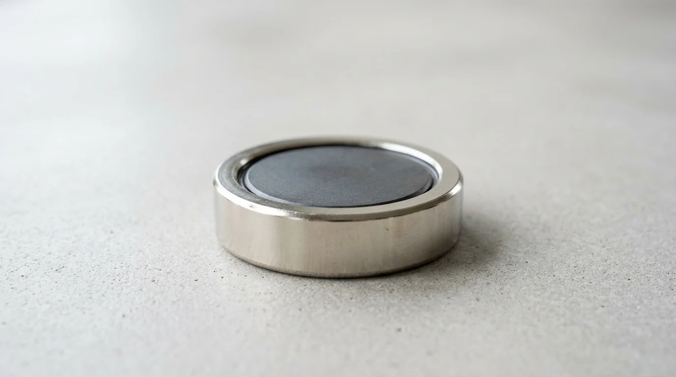
Small magnets can create big engineering problems when they chip, slip, or spread stray magnetic fields into nearby components. Pot magnets solve that challenge by combining a permanent magnet with a precisely formed steel housing that protects the magnetic core and concentrates force at the contact face. The result is a compact holding device with far greater practical pull strength than a bare magnet of similar size. For manufacturers, fixture builders, installers, and workshop users, understanding this design is essential for choosing the right holding force, mounting style, and material. This guide explains how pot magnets work, why their steel shell matters, and how to select them for reliable industrial use.
Why Pot Magnets Matter in Industrial Applications
In modern industrial engineering, securing components, fixtures, and heavy payloads requires non-destructive and highly reliable fastening solutions. While bare permanent magnets offer strong holding power, they often lack mechanical durability. Pot magnets—engineered assemblies featuring a permanent magnet encased in a ferromagnetic steel shell—solve this problem. Engineers integrate pot magnets into manufacturing, automation, and material handling to achieve robust temporary and semi-permanent fastening.
Understanding why these assemblies matter requires examining the mechanical and magnetic synergies that occur when raw magnetic materials are protected and focused by a precisely machined steel housing.
Performance Beyond Basic Magnetic Pull
Bare rare-earth magnets, particularly sintered neodymium-iron-boron (NdFeB), possess immense magnetic energy but are inherently brittle. In industrial environments characterized by heavy impacts, vibration, and repetitive clamping cycles, bare magnets frequently chip or crack. A pot magnet's low-carbon steel cup absorbs these mechanical shocks, shielding the brittle core from direct impact against mating surfaces.
This structural reinforcement significantly extends operational longevity. In repetitive, high-impact pick-and-place automation, the number of cycles a pot magnet survives before fracturing multiplies that of a bare magnet, depending on the exact forces and geometries involved. Additionally, the steel shell confines the magnetic field, preventing stray flux from interfering with nearby sensitive electronics. This localized containment is critical in precision engineering, where stray fields can induce errors in programmable logic controllers (PLCs) or distort telemetry data.
Commercial Problems Solved by High Holding Force
Industrial design frequently encounters strict spatial limitations where engineers must achieve maximum holding force within a minimal footprint. Pot magnets solve this commercial challenge by delivering disproportionately high pull forces relative to their physical size. For example, a standard 50mm diameter neodymium pot magnet can reliably generate a perpendicular holding force exceeding 100 kilograms under optimal, zero-air-gap conditions.
This high holding force density allows facilities to downsize fixtures, reduce the overall weight of robotic end-of-arm tooling (EOAT), and minimize sensor mount footprints. By deploying these high-strength, low-profile fasteners, operations eliminate complex mechanical clamps, drilling, or welding, thereby reducing installation times and material costs.
What a Pot Magnet Is and How It Works

To specify a pot magnet correctly, engineers must understand its internal architecture. A pot magnet is not merely a magnet glued into a metal cup; it is a carefully calculated assembly. It typically consists of the active magnet material, a low-carbon steel casing, and a non-magnetic spacer (often brass, aluminum, or epoxy) that separates the magnet from the steel shell to prevent the magnetic field from short-circuiting internally.
The physical interaction and precise tolerances between these components dictate the baseline characteristics of the assembly, setting the stage for how the magnetic field will ultimately behave.
How the Steel Shell Concentrates Magnetic Flux
The steel shell's most critical function is redirecting magnetic flux. In a bare cylindrical magnet, field lines radiate from the north pole, travel through the air, and return to the south pole, losing significant energy to the surrounding environment.
When embedded in a ferromagnetic steel cup, the shell acts as a highly permeable conduit. It gathers flux lines that would normally escape the back and sides, channeling them directly to the front working face. The cup's rim effectively becomes an opposing magnetic pole. This dual-pole concentration on a single operational plane substantially increases the active pull force compared to a bare magnet of the same volume. The exact increase varies based on specific magnet geometry, shell design, and flush contact with the target surface.
Key Magnet Materials: Neodymium, Ferrite, Samarium Cobalt, and Alnico
The performance of a pot magnet is heavily dictated by the core magnetic material housed within the shell. Engineers must select the appropriate material based on pull force requirements, operating temperatures, and environmental conditions.
| Material | Max Operating Temp | Corrosion Resistance | Relative Cost | Primary Industrial Use |
|---|---|---|---|---|
| Neodymium (NdFeB) | 80°C - 150°C | Low (Requires Plating) | High | Maximum holding force in compact spaces |
| Ferrite (Ceramic) | 250°C | Excellent | Low | Cost-sensitive, high-temp, or wet environments |
| Samarium Cobalt (SmCo) | 250°C - 350°C | High | Very High | High-temp aerospace and military applications |
| Alnico | 500°C+ | Good | Medium | Extreme temperature industrial ovens and welding |
Neodymium remains the industry standard for high-performance clamping, though its thermal degradation requires careful consideration in environments exceeding 80°C. For applications involving extreme heat, such as automotive paint curing ovens or deep-hole drilling equipment, Samarium Cobalt or Alnico cores become mandatory, despite their lower ambient pull force compared to NdFeB.
Pot Magnets vs Standard Magnets
While pot magnets offer superior clamping strength, their operational parameters differ vastly from standard bare magnets. The concentrated flux at the working face creates an intensely strong but incredibly shallow magnetic field. Consequently, pot magnets excel in zero-air-gap applications where the assembly sits flush against clean, flat steel.
Conversely, standard bare magnets project their magnetic fields much deeper into the surrounding space. If an application involves an air gap or requires the magnetic field to reach through a barrier, a bare magnet will often outperform a pot magnet. Specific examples include magnetic stirring in laboratories, triggering Hall-effect sensors from a distance, or holding fixtures through non-ferrous barriers like thick plastic, aluminum, or glass. Introducing a mere 1mm air gap between a pot magnet and its target can reduce the rated pull force by 50% to 70%, as the concentrated flux lines struggle to bridge the non-magnetic void.
Key Pot Magnet Specifications for Selection
Selecting the correct pot magnet requires rigorous evaluation of manufacturer specifications and an understanding of the mechanical forces at play in the intended application. Datasheets provide baseline metrics, but these numbers represent idealized laboratory conditions. Translating these specifications into real-world performance is critical for ensuring safety and operational reliability.
Buyers must navigate rated pull forces, mechanical integration methods, and complex load calculations to specify a magnet that will not fail under dynamic industrial conditions.
How to Interpret Rated Pull Force
The rated pull force listed on a pot magnet datasheet comes from a highly controlled testing environment. Industry-standard testing involves pulling the magnet perpendicularly away from a perfectly flat, machined, low-carbon steel test plate that is at least 10mm thick, with zero air gap and an ambient temperature of 20°C. Under these conditions, the magnet achieves its absolute maximum holding capacity.
In practice, manufacturer ratings systematically overstate real-world performance because actual industrial substrates are rarely this thick, flat, or clean. A critical caveat is that pot magnets require sufficiently thick ferrous targets to perform. On thin sheet metal, the steel shell itself can saturate the target material; the thin metal cannot absorb the full magnetic flux, causing a dramatic reduction in pull force—a major real-world failure mode. Furthermore, rated pull force strictly measures perpendicular tension. If the application involves shear forces—where the load attempts to slide the magnet down a vertical surface—the holding capacity drops precipitously.
Choosing Countersunk, Threaded, or Hook Designs
Pot magnets are designed for seamless mechanical integration, and the choice of housing dictates how the assembly mounts to fixtures or payloads. Countersunk pot magnets feature a central conical hole designed to accept standard flat-head screws (typically ranging from M3 to M8 sizes). This allows the magnet to bolt securely to a non-magnetic fixture while keeping the screw head flush with the working face, ensuring zero air gap.
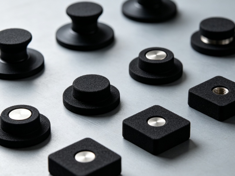
Threaded designs offer alternative mounting strategies. Internal threaded (female) studs allow the magnet to screw onto existing threaded rods or machine mounts, while external threaded (male) studs can pass through a housing and secure with a standard hex nut. For material handling, routing cables, or suspending tools, pot magnets equipped with integrated hooks or eyebolts provide immediate, tool-less utility. The selection among these designs depends entirely on whether the magnet is the moving component, the stationary fixture, or a temporary suspension point.
Calculating Load and Safety Factors
Relying solely on the maximum rated pull force without applying appropriate safety factors is a critical engineering error that can lead to equipment damage or severe injury. When calculating the required load capacity, engineers must apply a safety multiplier based on the nature of the application and the orientation of the load.
| Application Load Type | Description | Recommended Safety Factor |
|---|---|---|
| Static Load (Ideal) | No movement, perpendicular pull, clean 10mm steel | 1:2 to 1:3 |
| Shear Load | Sliding force parallel to the mounting surface | 1:4 to 1:5 |
| Dynamic/Vibrating Load | Subject to mechanical shocks or machinery vibration | 1:5 to 1:8 |
| Overhead Lifting | Human safety risk or critical payload suspension | 1:10 or higher |
Shear loads are notoriously weak for standard pot magnets because smooth steel-on-steel contact offers very little friction. To counteract this sliding tendency, engineers must often specify rubber-coated pot magnets or integrate mechanical stops. For example, if an engineering team needs to suspend a 10 kg static payload vertically (perpendicular pull), they should specify a magnet with a rated pull force of at least 30 kg (1:3 safety factor). If that same 10 kg payload must be held against a vertical wall (shear load), the required rated pull force may jump to 50 kg or more to prevent sliding.
Quality, Compliance, and Sourcing Considerations
Procuring pot magnets for enterprise-scale applications involves navigating a complex global supply chain. Beyond the basic dimensions and magnetic grades, buyers must scrutinize manufacturing tolerances, surface treatments, and specific magnetic risks to ensure the final product meets industrial standards.
Understanding the cost drivers and necessary quality documentation allows procurement managers to balance upfront expenditures with long-term reliability, avoiding the hidden costs associated with premature magnet failure.
Material Grades, Plating, and Coating Thickness
The specification of the raw magnetic material dictates the baseline performance, with NdFeB grades ranging from N35 (standard strength) to N52 (maximum strength), or specialized high-temperature grades like N42SH. Because neodymium is highly susceptible to oxidation, the plating and coating of the pot magnet assembly are equally critical. The industry standard is a triple-layer Nickel-Copper-Nickel (Ni-Cu-Ni) plating, typically applied at a thickness of 10 to 20 microns. This provides adequate protection for dry, indoor industrial environments.
For outdoor applications or marine environments, standard plating is insufficient. Engineers must specify zinc plating, epoxy coatings, or thick rubber encasements. Rubber-coated pot magnets are particularly valuable as they provide superior corrosion resistance and significantly increase the coefficient of friction, thereby improving shear load capacity. However, buyers must mathematically account for the rubber layer, which introduces a continuous air gap that inherently reduces the perpendicular magnetic pull force, as governed by the gap sensitivity principles discussed earlier.
Compliance and Quality Documents to Request
Mitigating supply chain risks for critical applications means procurement teams should request appropriate quality and compliance documentation from manufacturers. At a minimum, suppliers should provide certificates of compliance for RoHS and REACH directives, ensuring the assemblies are free from restricted heavy metals.
Beyond basic compliance, buyers must focus on magnet-unique risks. Procurement teams should request Material Test Reports (MTRs) to verify the exact grade of the magnetic core, as well as documentation verifying magnetization consistency and pole alignment tolerances, since slight deviations can drastically alter holding force. Furthermore, improper handling or inadequate shielding during shipping can lead to irreversible demagnetization. Ensuring suppliers use magnetically shielded packaging and adhere to strict handling protocols is a critical quality checkpoint.
Cost Drivers in Pot Magnet Procurement
Several variables dictate the unit price of pot magnets, starting with the fluctuating commodity prices of rare-earth elements like neodymium and dysprosium. However, the machining of the steel shell often represents a significant portion of the total cost. Standard pot magnets are machined with standard tolerances (typically ±0.1mm). Demanding tighter tolerances for high-precision aerospace or robotic integrations will substantially increase machining times and scrap rates, driving up costs.
Custom tooling also plays a major role in procurement economics. While standard catalog sizes are readily available, custom dimensions or specialized thread pitches require bespoke CNC programming. Non-Recurring Engineering (NRE) costs for custom pot magnet assemblies can range from $500 to $2,000. Therefore, whenever possible, engineers should design fixtures around standard, commercially available pot magnet dimensions to optimize the total cost of ownership.
How to Decide if a Pot Magnet Is the Right
Choosing between a pot magnet and a standard bare magnet is a pivotal decision in the mechanical design process. Making the correct choice requires a holistic view of the application's physical environment, the required holding force, and the lifecycle expectations of the assembly.
By applying a structured decision-making framework, engineers can definitively determine whether the added cost and weight of a steel shell are justified by the operational benefits.
When Pot Magnets Outperform Bare Magnets
Pot magnets categorically outperform bare magnets in applications requiring maximum clamping force upon direct contact with a ferrous surface. If the primary objective is to hold a fixture rigid, suspend heavy tooling, or secure an access panel without drilling holes, the pot magnet is the superior choice.
Additionally, in environments prone to mechanical shock—such as stamping presses, conveyor systems, or heavy automated machinery—the protective steel casing is non-negotiable. Because bare neodymium is vulnerable to impact damage, the protective casing prevents equipment downtime and potential contamination of the product stream. Conversely, pot magnets should be avoided in applications requiring magnetic sensing over large distances, or when attempting to separate tramp iron from deep streams of bulk materials, as their shallow magnetic field will fail to reach the target.
Final Decision Framework for Buyers
To finalize the selection process, buyers and engineers should use the following decision matrix to choose between a pot magnet and a bare magnet:
- If the application requires maximum holding force in a constrained footprint and flush contact with thick steel: Choose a Pot Magnet. The steel shell maximizes pull force density.
- If the application involves heavy impacts, vibration, or repetitive mechanical clamping: Choose a Pot Magnet. The steel housing prevents the brittle magnetic core from fracturing.
- If the application requires the magnetic field to penetrate through thick air gaps, non-ferrous barriers, or perform distant sensing: Choose a Bare Magnet. A pot magnet's shallow field will fail to reach the target.
- If the load involves significant shear (sliding) forces on a vertical surface: Choose a Rubber-Coated Pot Magnet and apply a 1:5 safety factor. The rubber increases friction, though you must account for the inherent air gap it introduces.
- If the operating environment exceeds 80°C: Choose a Pot Magnet with a Samarium Cobalt or Alnico core, but account for the steel shell's thermal expansion and potential loss of permeability at high temperatures. Additionally, note that Alnico's low coercivity makes it vulnerable to demagnetization from mechanical shock, even within a protective pot.
Key Takeaways
- A pot magnet uses a steel cup to protect a brittle permanent magnet and focus magnetic flux toward the working face for higher usable holding force.
- A 50 mm neodymium pot magnet can exceed 100 kg of perpendicular holding force under ideal zero-air-gap conditions on suitable steel.
- The rated pull force of a pot magnet drops when there is paint, rust, curvature, thin steel, vibration, or any air gap between the magnet and target surface.
- Neodymium pot magnets are best for compact high-strength holding, while ferrite pot magnets offer a cost-effective choice for many light to heavy-duty mounting tasks.
- Choose the mounting style—straight hole, countersunk hole, threaded stud, internal thread, hook, or eyelet—based on how the magnet will be installed and loaded.
Frequently Asked Questions
What is a pot magnet?
A pot magnet is a magnetic assembly that places a permanent magnet, often NdFeB or ferrite, inside a steel cup. The steel housing protects the brittle magnet and redirects magnetic flux toward the holding face for stronger, more controlled attachment.
Why is a pot magnet stronger than a standard magnet?
A pot magnet is stronger on its working face because the steel shell concentrates magnetic flux into one contact surface. This increases pull force against flat ferromagnetic steel, especially when the surface is clean, thick, and has minimal air gap.
What reduces the holding force of a pot magnet?
Air gaps, paint, rust, curved surfaces, thin steel, vibration, and side loads all reduce holding force. Rated pull force is usually measured under ideal perpendicular conditions on thick, flat steel, so real-world performance should include a safety margin.
Are neodymium pot magnets better than ferrite pot magnets?
Neodymium pot magnets deliver higher pull force in a compact size, making them ideal for fixtures, hooks, and lifting-style tools. Ferrite pot magnets are more cost-effective and corrosion-resistant, making them suitable for lower-cost holding and mounting applications.
Can pot magnets be used for outdoor applications?
Yes, but the right design matters. For outdoor or wet environments, consider protective coatings, stainless or rubber-coated housings, or application-specific assemblies. Richeng supplies options such as rubber-coated magnets and fishing magnets for demanding environments.