 EN
EN AR
AR HR
HR CS
CS DA
DA NL
NL FI
FI FR
FR DE
DE EL
EL IT
IT JA
JA KO
KO NO
NO PL
PL PT
PT RU
RU ES
ES SV
SV IW
IW VI
VI TH
TH TR
TR FA
FA MS
MS- Pot magnet holding strength depends on the steel cup, air gap, and load direction, not only on magnet grade.
- Internal thread mounting is best when the design needs clean fastening, repeatable assembly, and easy replacement.
- Flexible mounting designs should be checked for thread compatibility, corrosion, temperature, and surface flatness before installation.
- Shear and peel loads can reduce usable holding force far below the rated pull force.
- For reliable selection, compare pull force, thread spec, coating, and working environment together.
Internal thread pot magnet installation is best understood as a load-transfer problem, not just a fastening task, because the steel cup concentrates magnetic flux and can deliver much higher usable holding force than a bare magnet of the same size. In many engineering applications, the real performance limit is the interface: surface flatness, coating integrity, thread engagement, and load direction. When precision matters, tolerance control follows familiar metrology logic such as the general geometric tolerancing framework in ISO 1101, while magnet performance should be validated against measured pull conditions rather than assumed from catalog numbers alone. For users comparing mounting styles, internal thread models sit between permanent bonded solutions and removable hardware like pot magnets, magnetic hooks, and rubber coated magnets.
What an Internal Thread Pot Magnet Is and Why the Cup Matters
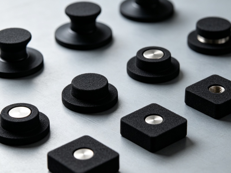
An internal thread pot magnet is a neodymium or ferrite magnet housed in a steel cup with a threaded hole for direct mounting.
The steel cup is not just a shell; it closes part of the magnetic circuit and focuses flux toward the contact face, which is why pot magnets often outperform exposed magnets in practical holding applications. This magnetic circuit effect also improves durability, because the steel housing shields the brittle magnet material from impact, chipping, and edge damage during assembly. In environments with moisture or cleaning chemicals, surface protection matters as much as magnet grade, which is why nickel, epoxy, or rubber-based coatings are selected according to corrosion exposure.
For design teams, the key advantage of internal threading is packaging flexibility. A threaded insert allows the magnet to be mounted on brackets, plates, frames, and adjustable fixtures without adhesives. That makes the component useful in modular equipment, jigs, enclosure doors, display systems, and removable holding points where service access is important.
| Feature | Internal Thread Pot Magnet | Bare Neodymium Magnet | Why It Matters |
|---|---|---|---|
| Housing | Steel cup | None | Cup improves flux concentration and protection |
| Mounting | Threaded insert | Adhesive or external clamp | Threaded fastening improves repeatability |
| Damage resistance | Higher | Lower | Less chipping during assembly |
| Usable holding force | Higher in direct contact | Lower in many mounted cases | Real performance depends on the interface |
For deeper product comparison, the mounting logic is similar to other engineered magnetic assemblies such as threaded magnets and industrial pot magnet assemblies, where the design goal is controlled attachment rather than raw magnet strength alone.
How to Install Internal Thread Pot Magnet for Flexible Mounting Designs
Correct installation starts with matching the thread, the load path, and the contact surface.
Step one is to confirm the thread specification in the magnet body and the mating fastener. Internal threads are commonly produced in metric and imperial forms, and a mismatch can strip the insert or create partial engagement that fails under vibration. Step two is to verify the working load direction. Pot magnets are strongest in direct pull, but shear and peel loads reduce capacity sharply because the holding force depends on intimate face contact. Step three is to prepare the contact surface so the steel cup can sit flush. Paint, burrs, scale, and curvature increase the air gap and reduce effective attraction.
In practical assembly, a washer is often used to spread clamp load and prevent localized stress on the threaded socket. If the design includes repeated removal, use a torque-controlled fastener rather than hand tightening alone. For removable fixtures, engineers often design for serviceability by selecting a mounting stack that can be disassembled without disturbing alignment.
- Verify thread size, pitch, and available engagement length.
- Clean the contact face and remove coatings only where allowed by the design.
- Align the magnet so the working face sits flat against the target surface.
- Use a compatible screw, washer, and torque limit for the substrate.
- Test in the actual load direction: pull, shear, and vibration if applicable.
For flexible mounting designs, this is the stage where many failures are prevented. A magnet that looks strong in a catalog may underperform if it is mounted to a painted, curved, or nonferromagnetic surface, so the design should be validated on the exact substrate rather than a generic test plate.
Key Engineering Data for Pot Magnet Installation
Magnet installation succeeds when the design respects measurable parameters.
One useful reference is temperature. According to NIST guidance on SI usage, dimensional and unit consistency is essential in engineering work, and magnet design is no exception. For neodymium systems, typical commercial grades are often selected by maximum operating temperature: standard grades around 80 C, high-temperature grades around 120 C to 150 C, and specialty grades above that range depending on the manufacturer. These temperature limits matter because irreversible demagnetization risk rises when the application exceeds the magnet’s rated environment.
Another useful reference is surface roughness. For metal-to-metal contact, a smoother mating face improves repeatability because it reduces microscopic air gaps. In real installations, even a small gap can materially reduce holding force, which is why a magnet rated for high pull on a polished steel plate may perform notably worse on powder-coated or uneven steel. A design with a 0.2 mm coating thickness on both sides can add enough separation to change usable force in a way the user feels immediately.
| Parameter | Typical Value | Why It Matters |
|---|---|---|
| Working temperature for standard neodymium grades | About 80 C | Prevents thermal loss of magnetization |
| High-temperature grade range | About 120 C to 150 C | Useful for motors, enclosures, and outdoor heat |
| Coating thickness impact | 0.1 mm to 0.2 mm per side | Can create a meaningful air gap |
| Practical contact condition | Near-zero gap | Maximizes holding force |
For dimensional control and fit considerations, the same engineering mindset used in ISO 2768 helps teams specify what matters and avoid over-tolerancing noncritical features. In magnet mounting, thread fit, face flatness, and substrate condition are usually more important than decorative finish.
Load Direction, Pull Force, and Real-World Performance
Rated pull force is only the starting point for selecting an internal thread pot magnet.
Manufacturers usually measure pull force under ideal conditions: clean, thick, low-carbon steel of sufficient thickness, direct perpendicular separation, and full contact. Real installations rarely match those test conditions. If the load acts sideways, the usable force can drop dramatically because the magnet is now resisting friction and sliding rather than direct separation. If the target is thin steel, force also falls because the magnetic circuit saturates differently and flux leaks through the backing material.
This is why many experienced buyers compare two values: pull force and shear resistance. Pull force tells you how hard it is to lift the magnet straight off. Shear resistance tells you how well it stays put when the load tries to slide it off the surface. For movable fixtures, signage, and adjustable tooling, shear is often the more relevant metric.
| Load Condition | Effect on Holding | Design Response |
|---|---|---|
| Direct pull | Highest usable force | Best for vertical separation loads |
| Shear load | Lower than pull | Use higher friction or mechanical backup |
| Peel load | Often the weakest condition | Increase contact area and reduce lever arm |
| Vibration | Can loosen fasteners over time | Use locking hardware or thread treatment |
ISO test logic supports this careful distinction between ideal and service conditions. Magnetic force should be evaluated in the same environment the part will actually see, not only in a lab setup. That approach is also consistent with the traceability mindset in NIST metrology guidance and is one reason why engineering teams validate sample assemblies before full production.
Choosing the Right Flexible Mounting Design
The best mounting design is the one that matches the job, not the strongest magnet on paper.
Flexible mounting means the magnet may need to be removed, repositioned, tilted, or combined with other hardware. In that case, internal threading is valuable because it supports modular assembly. However, flexibility also increases the chance of misuse. If the magnet is used on a curved machine housing, for example, the actual contact area may be small, and a smaller contact area increases local stress and reduces usable force.

For corrosion-prone or scratch-sensitive surfaces, rubber coated solutions may be better than exposed cup magnets because they reduce surface damage and improve friction stability. For exposed steel enclosures, an internal thread pot magnet is often a cleaner choice when the design needs hidden fastening and simple replacement. When the mounting point needs frequent adjustment, a threaded magnet paired with an articulated arm or bracket can create a stronger system than a larger magnet alone.
- Use internal thread pot magnets when you need removable, threaded installation.
- Use rubber coated magnets when surface protection and anti-slip behavior matter.
- Use a larger contact face when the load has a long lever arm.
- Use a mechanical backup when vibration or shock is expected.
In product planning, flexible mounting designs often succeed when the magnet is treated as one part of a system rather than the entire solution. That is especially true in industrial fixtures, machine guards, access panels, and mobile accessories where the load can change over time.
Common Installation Mistakes and How to Avoid Them
Most pot magnet failures come from interface mistakes, not from magnet material defects.
The first mistake is overestimating catalog pull force. If the test plate used by the supplier is thicker and flatter than the customer’s real substrate, the actual performance will be lower. The second mistake is ignoring thread depth. Partial thread engagement can strip an insert under repeated use, especially if the screw bottoms out before clamping force is reached. The third mistake is relying on the magnet alone where a fastener lock is needed. Vibration can loosen the system if the thread is not secured.
The fourth mistake is applying the magnet to a coated, rusted, or curved surface and expecting laboratory performance. The fifth mistake is using a high-temperature process near a standard magnet grade. If the assembly passes through heat exposure during curing, welding-adjacent work, or outdoor thermal cycling, grade selection must be checked first.
- Do not compare magnets only by size.
- Do not ignore coating thickness or paint layers.
- Do not use insufficient thread engagement.
- Do not assume pull force equals shear strength.
- Do not skip environment checks for moisture, heat, and corrosion.
A careful buyer will also review related mounting families such as magnetic hooks and magnetic bases to understand where a threaded cup magnet is the better tool and where another geometry is more practical.
Installation Checklist for Buyers and Engineers
A short checklist reduces field failures more effectively than post-installation troubleshooting.
| Checklist Item | Target | Risk If Ignored |
|---|---|---|
| Thread compatibility | Exact match | Stripped insert or loose fit |
| Surface flatness | Clean, even contact | Lower holding force |
| Load direction | Direct pull preferred | Unexpected slip or peel-off |
| Temperature rating | Above operating peak | Demagnetization |
| Corrosion protection | Matched to environment | Coating failure and reduced life |
When teams evaluate suppliers, they often ask for pull data, coating details, thread specification, and test conditions in the same document. That is a good practice because it makes the selection process auditable. It also helps procurement teams compare products across vendors without mixing up different test methods.
For additional technical reference, the structure of force testing and dimensional specification is more trustworthy when it aligns with recognized standards such as ASTM E4 for force verification and ISO 9001 for process consistency. These are not magnet-specific standards, but they strengthen the discipline behind selection, inspection, and documentation.
FAQ
How do I know which thread size to choose for an internal thread pot magnet?
Choose the thread size that matches both the fastener and the available engagement depth, then verify the clamping load and substrate thickness. A correct thread fit is more important than choosing the largest possible size.
Why does a pot magnet hold better than a bare neodymium magnet?
The steel cup concentrates magnetic flux toward the working face and shields the sides, which increases usable holding force on direct-contact steel surfaces.
Can I use an internal thread pot magnet on a painted surface?
Yes, but performance will usually drop because the paint creates an air gap. If holding force is critical, test the exact painted surface before finalizing the design.
What is the difference between pull force and shear force?
Pull force measures straight-off separation, while shear force measures resistance to sliding. Many mounting failures happen in shear, so both values matter.
What temperature limit should I check before installation?
Check the magnet grade and its rated operating temperature. Standard neodymium grades are often used around 80 C, while higher-temperature grades can be designed for roughly 120 C to 150 C.
How can I make a flexible mounting design more reliable?
Use a flat contact face, correct thread engagement, the right coating, and a mechanical backup if vibration is expected. Flexibility should not replace structural stability.
When should I choose rubber coated magnets instead?
Choose rubber coated magnets when the surface must be protected from scratches or when higher friction and lower surface wear are more important than maximum direct pull.
For buyers who need a broader product context, the mounting families in pot magnets, rubber coated magnets, and magnetic hooks show how different geometries solve different installation problems while sharing the same basic principle: control the magnetic circuit, then control the interface.